↧
Camera calibration With OpenCV
↧
Matlab下载
http://www.ilovematlab.com/thread-526724-1-1.html?s_tid=LandingPageTabqa
http://blog.sina.com.cn/s/blog_14d1511ee0102wxi4.html
Matlab2017a
链接: https://pan.baidu.com/s/1gflAa2Z 密码: fwrx
软件安装教程链接:http://t.cn/RVTJgqZ
楼主亲测的安装教程在这里,觉得有用的话为我写的百度经验点个赞吧?^_^
http://jingyan.baidu.com/article/ac6a9a5e0e67652b653eacc2.html
===================================================
Matlab2016b?
安装包链接:http://pan.baidu.com/s/1mhUrAEO 密码:8oo0??
破解crack?
链接:http://pan.baidu.com/s/1hsDLdVQ 密码:zggs?
Matlab2016a
链接:http://pan.baidu.com/s/1miwD828 密码:tt7s
Matlab2015a
链接:http://pan.baidu.com/s/1dEMZYud 密码:lfg0
Matlab2014a
链接:http://pan.baidu.com/s/1mihe2xi 密码:6ps0
Matlab2013a
链接:http://pan.baidu.com/s/1qYnbXW4 密码:c7me
Matlab2012a
链接:http://pan.baidu.com/s/1qYKlW2C 密码:funt
Matlab2011a
链接:http://pan.baidu.com/s/1eSLmv1w 密码:0acg
Matlab2010a
链接:http://pan.baidu.com/s/1eSr0fiq 密码:f83e
Matlab2009a
链接:http://pan.baidu.com/s/1kUKLT5P 密码:ormj
Matlab2008a
链接:http://pan.baidu.com/s/1nvAiGBn 密码:iogy
↧
↧
鱼眼相机标定以及OpenCV实现
↧
CSE/EE486 Computer Vision I
http://www.cse.psu.edu/~rtc12/CSE486/
https://stackoverflow.com/questions/10163034/how-can-i-calculate-camera-position-by-comparing-two-photographs
In addition to slides that I created, I borrowed heavily from other lecturers whose computer vision slides are on the web. I used to put an attribution at the bottom of each slide as to where and who it came from. However, that led to cluttered slides, and was distracting. So, I dropped that format. Instead, I'm telling you up-front that a lot of the slides in the lectures below did not originate from me. Here is a partial list of the main sources that I can remember: Octavia Camps, Forsyth and Ponce, David Jacobs, Steve Seitz, Chuck Dyer, Martial Hebert. If I forgot you, and you see your slides here, well... thanks. And drop me a line so I can add your name to the list.
By the same token, if you are putting together a computer vision course, and want to use some of my slides, go right ahead. You are welcome to them, since the main goal here is to improve the quality of computer vision education everywhere. To quote Thomas Jefferson: "He who receives an idea from me, receives instruction himself without lessening mine; as he who lights his taper at mine, receives light without darkening me. That ideas should freely spread from one to another over the globe, for the moral and mutual instruction of man, and improvement of his condition, seems to have been peculiarly and benevolently designed by nature, when she made them, like fire, expansible over all space, without lessening their density at any point, and like the air in which we breathe, move, and have our physical being, incapable of confinement or exclusive appropriation." Jefferson was one awesome dude.
Background
I have taught this course several times (almost every semester). I am always fiddling around with the course content, so the material covered and the order of presentation changes from semester to semester. Below are the lecture notes from Fall 2007.In addition to slides that I created, I borrowed heavily from other lecturers whose computer vision slides are on the web. I used to put an attribution at the bottom of each slide as to where and who it came from. However, that led to cluttered slides, and was distracting. So, I dropped that format. Instead, I'm telling you up-front that a lot of the slides in the lectures below did not originate from me. Here is a partial list of the main sources that I can remember: Octavia Camps, Forsyth and Ponce, David Jacobs, Steve Seitz, Chuck Dyer, Martial Hebert. If I forgot you, and you see your slides here, well... thanks. And drop me a line so I can add your name to the list.
By the same token, if you are putting together a computer vision course, and want to use some of my slides, go right ahead. You are welcome to them, since the main goal here is to improve the quality of computer vision education everywhere. To quote Thomas Jefferson: "He who receives an idea from me, receives instruction himself without lessening mine; as he who lights his taper at mine, receives light without darkening me. That ideas should freely spread from one to another over the globe, for the moral and mutual instruction of man, and improvement of his condition, seems to have been peculiarly and benevolently designed by nature, when she made them, like fire, expansible over all space, without lessening their density at any point, and like the air in which we breathe, move, and have our physical being, incapable of confinement or exclusive appropriation." Jefferson was one awesome dude.
Fall 2007 Lecture Notes
Detailed List of Topics Covered in Fall 2007| Lecture 01: Intro to Computer Vision | slides | 6 per page |
| Lecture 02: Intensity Surfaces and Gradients | slides | 6 per page |
| Lecture 03: Linear Operators and Convolution | slides | 6 per page |
| Lecture 04: Smoothing | slides | 6 per page |
| Lecture 05: Edge Detection | slides | 6 per page |
| Lecture 06: Corner Detection | slides | 6 per page |
| Lecture 07: Template Matching | slides | 6 per page |
| Lecture 08: Introduction to Stereo | slides | 6 per page |
| Lecture 09: Stereo Algorithms | slides | 6 per page |
| Lecture 10: Image Pyramids | slides | 6 per page |
| Lecture 11: LoG Edge and Blob Finding | slides | 6 per page |
| Lecture 12: Camera Projection (Extrinsics) | slides | 6 per page |
| Lecture 13: Camera Projection (Intrinsics) | slides | 6 per page |
| Lecture 14: Parameter Estimation; Image Warping | slides | 6 per page |
| Lecture 15: Robust Estimation: RANSAC | slides | 6 per page |
| Lecture 16: Planar Homographies | slides | 6 per page |
| Lecture 17: Stabilization and Mosaicing | slides | 6 per page |
| Lecture 18: Generalized Stereo | slides | 6 per page |
| Lecture 19: Essential and Fundamental Matrices | slides | 6 per page |
| Lecture 20: The 8-point algorithm | slides | 6 per page |
| Lecture 21: Stereo Reconstruction | slides | 6 per page |
| Lecture 22: Camera Motion Field | slides | 6 per page |
| Lecture 23: Optic Flow | slides | 6 per page |
| Lecture 24: Video Change Detection | slides | 6 per page |
| Lecture 25: Structure From Motion (SFM) | slides | 6 per page |
| Lecture 26: Color and Light | slides | 6 per page |
| Lecture 27: Application: Skin Color | slides | 6 per page |
| Lecture 28: Intro to Tracking | slides | 6 per page |
| Lecture 29: Video Tracking: Mean-shift | slides | 6 per page |
| Lecture 30: Video Tracking: Lucas-Kanade | slides | 6 per page |
| Lecture 31: Object Recognition : SIFT Keys | slides | 6 per page |
| Lecture 32: Object Recognition : PCA / Eigenfaces | slides | 6 per page |
↧
How to tranform 2D image coordinates to 3D world coordinated with Z = 0?
http://answers.opencv.org/question/150451/how-to-tranform-2d-image-coordinates-to-3d-world-coordinated-with-z-0/
https://github.com/opencv/opencv/issues/8762
https://github.com/opencv/opencv/issues/8762
Hi everyone, I currently working on my project which involves vehicle detection and tracking and estimating and optimizing a cuboid around the vehicle. For that I am taking the center of the detected vehicle and I need to find the 3D world coodinate of the point and then estimate the world coordinates of the edges of the cuboid and the project it back to the image to display it.
So, now I am new to computer vision and OpenCV, but in my knowledge, I just need 4 points on the image and need to know the world coordinates of those 4 points and use solvePNP in OpenCV to get the rotation and translation vectors (I already have the camera matrix and distortion coefficients). Then, I need to use Rodrigues to transform the rotation vector into a rotation matrix and then concatenate it with the translation vector to get my extrinsic matrix and then multiply the extrinsic matrix with the camera matrix to get my projection matrix. Since my z coordinate is zero, so I need to take off the third column from the projection matrix which gives the homography matrix for converting the 2D image points to 3D world points. Now, I find the inverse of the homography matrix which gives me the homography between the 3D world points to 2D image points. After that I multiply the image points [x, y, 1]t with the inverse homography matrix to get [wX, wY, w]t and the divide the entire vector by the scalar w to get [X, Y, 1] which gives me the X and Y values of the world coordinates.
My code is like this:
image_points.push_back(Point2d(275, 204));
image_points.push_back(Point2d(331, 204));
image_points.push_back(Point2d(331, 308));
image_points.push_back(Point2d(275, 308));
cout << "Image Points: " << image_points << endl << endl;
world_points.push_back(Point3d(0.0, 0.0, 0.0));
world_points.push_back(Point3d(1.775, 0.0, 0.0));
world_points.push_back(Point3d(1.775, 4.620, 0.0));
world_points.push_back(Point3d(0.0, 4.620, 0.0));
cout << "World Points: " << world_points << endl << endl;
solvePnP(world_points, image_points, cameraMatrix, distCoeffs, rotationVector, translationVector);
cout << "Rotation Vector: " << endl << rotationVector << endl << endl;
cout << "Translation Vector: " << endl << translationVector << endl << endl;
Rodrigues(rotationVector, rotationMatrix);
cout << "Rotation Matrix: " << endl << rotationMatrix << endl << endl;
hconcat(rotationMatrix, translationVector, extrinsicMatrix);
cout << "Extrinsic Matrix: " << endl << extrinsicMatrix << endl << endl;
projectionMatrix = cameraMatrix * extrinsicMatrix;
cout << "Projection Matrix: " << endl << projectionMatrix << endl << endl;
double p11 = projectionMatrix.at<double>(0, 0),
p12 = projectionMatrix.at<double>(0, 1),
p14 = projectionMatrix.at<double>(0, 3),
p21 = projectionMatrix.at<double>(1, 0),
p22 = projectionMatrix.at<double>(1, 1),
p24 = projectionMatrix.at<double>(1, 3),
p31 = projectionMatrix.at<double>(2, 0),
p32 = projectionMatrix.at<double>(2, 1),
p34 = projectionMatrix.at<double>(2, 3);
homographyMatrix = (Mat_<double>(3, 3) << p11, p12, p14, p21, p22, p24, p31, p32, p34);
cout << "Homography Matrix: " << endl << homographyMatrix << endl << endl;
inverseHomographyMatrix = homographyMatrix.inv();
cout << "Inverse Homography Matrix: " << endl << inverseHomographyMatrix << endl << endl;
Mat point2D = (Mat_<double>(3, 1) << image_points[0].x, image_points[0].y, 1);
cout << "First Image ...
https://github.com/opencv/opencv/issues/8762
- OpenCV => 3.2
- Operating System / Platform => Windows 64 Bit
- Compiler => Visual Studio 2015
Hi everyone, I understand that this forum is to report bugs and not to ask questions but I already posted about my problems in answers.opencv.org without any useful response. I need to resolve my problem very urgently since my final year project deadline is approaching soon.
I am currently working on my project which involves vehicle detection and tracking and estimating and optimizing a cuboid around the vehicle. For that I have accomplished detection and tracking of vehicles and I need to find the 3-D world coordinates of the image points of the edges of the bounding boxes of the vehicles and then estimate the world coordinates of the edges of the cuboid and the project it back to the image to display it.
So, I am new to computer vision and OpenCV, but in my knowledge, I just need 4 points on the image and need to know the world coordinates of those 4 points and use solvePNP in OpenCV to get the rotation and translation vectors (I already have the camera matrix and distortion coefficients). Then, I need to use Rodrigues to transform the rotation vector into a rotation matrix and then concatenate it with the translation vector to get my extrinsic matrix and then multiply the extrinsic matrix with the camera matrix to get my projection matrix. Since my z coordinate is zero, so I need to take off the third column from the projection matrix which gives the homography matrix for converting the 2D image points to 3D world points. Now, I find the inverse of the homography matrix which gives me the homography between the 3D world points to 2D image points. After that I multiply the image points [x, y, 1]t with the inverse homography matrix to get [wX, wY, w]t and the divide the entire vector by the scalar w to get [X, Y, 1] which gives me the X and Y values of the world coordinates.
My code looks like this:
#include "opencv2/opencv.hpp" #include <stdio.h> #include <iostream> #include <sstream> #include <math.h> #include <conio.h> using namespace cv; using namespace std; Mat cameraMatrix, distCoeffs, rotationVector, rotationMatrix, translationVector, extrinsicMatrix, projectionMatrix, homographyMatrix, inverseHomographyMatrix; Point point; vector<Point2d> image_points; vector<Point3d> world_points; int main() { FileStorage fs1("intrinsics.yml", FileStorage::READ); fs1["camera_matrix"] >> cameraMatrix; cout << "Camera Matrix: " << cameraMatrix << endl << endl; fs1["distortion_coefficients"] >> distCoeffs; cout << "Distortion Coefficients: " << distCoeffs << endl << endl; image_points.push_back(Point2d(275, 204)); image_points.push_back(Point2d(331, 204)); image_points.push_back(Point2d(331, 308)); image_points.push_back(Point2d(275, 308)); cout << "Image Points: " << image_points << endl << endl; world_points.push_back(Point3d(0.0, 0.0, 0.0)); world_points.push_back(Point3d(1.775, 0.0, 0.0)); world_points.push_back(Point3d(1.775, 4.620, 0.0)); world_points.push_back(Point3d(0.0, 4.620, 0.0)); cout << "World Points: " << world_points << endl << endl; solvePnP(world_points, image_points, cameraMatrix, distCoeffs, rotationVector, translationVector); cout << "Rotation Vector: " << endl << rotationVector << endl << endl; cout << "Translation Vector: " << endl << translationVector << endl << endl; Rodrigues(rotationVector, rotationMatrix); cout << "Rotation Matrix: " << endl << rotationMatrix << endl << endl; hconcat(rotationMatrix, translationVector, extrinsicMatrix); cout << "Extrinsic Matrix: " << endl << extrinsicMatrix << endl << endl; projectionMatrix = cameraMatrix * extrinsicMatrix; cout << "Projection Matrix: " << endl << projectionMatrix << endl << endl; double p11 = projectionMatrix.at<double>(0, 0), p12 = projectionMatrix.at<double>(0, 1), p14 = projectionMatrix.at<double>(0, 3), p21 = projectionMatrix.at<double>(1, 0), p22 = projectionMatrix.at<double>(1, 1), p24 = projectionMatrix.at<double>(1, 3), p31 = projectionMatrix.at<double>(2, 0), p32 = projectionMatrix.at<double>(2, 1), p34 = projectionMatrix.at<double>(2, 3); homographyMatrix = (Mat_<double>(3, 3) << p11, p12, p14, p21, p22, p24, p31, p32, p34); cout << "Homography Matrix: " << endl << homographyMatrix << endl << endl; inverseHomographyMatrix = homographyMatrix.inv(); cout << "Inverse Homography Matrix: " << endl << inverseHomographyMatrix << endl << endl; Mat point2D = (Mat_<double>(3, 1) << image_points[0].x, image_points[0].y, 1); cout << "First Image Point" << point2D << endl << endl; Mat point3Dw = inverseHomographyMatrix*point2D; cout << "Point 3D-W : " << point3Dw << endl << endl; double w = point3Dw.at<double>(2, 0); cout << "W: " << w << endl << endl; Mat matPoint3D; divide(w, point3Dw, matPoint3D); cout << "Point 3D: " << matPoint3D << endl << endl; _getch(); return 0; }
I have got the image coordinates of the four known world points and hard-coded it for simplification.image_points contain the image coordinates of the four points and world_points contain the world coordinates of the four points. I am considering the the first world point as the origin (0, 0, 0) in the world axis and using known distance calculating the coordinates of the other four points. Now after calculating the inverse homography matrix, I multiplied it with [image_points[0].x, image_points[0].y, 1]t which is related to the world coordinate (0, 0, 0). Then I divide the result by the third component w to get [X, Y, 1]. But after printing out the values of X and Y, it turns out they are not 0, 0 respectively. What am doing wrong?
The output of my code is like this:
Camera Matrix: [517.0036881709533, 0, 320; 0, 517.0036881709533, 212; 0, 0, 1] Distortion Coefficients: [0.1128663679798094; -1.487790079922432; 0; 0; 2.300571896761067] Image Points: [275, 204; 331, 204; 331, 308; 275, 308] World Points: [0, 0, 0; 1.775, 0, 0; 1.775, 4.62, 0; 0, 4.62, 0] Rotation Vector: [0.661476468596541; -0.02794460022559267; 0.01206996342819649] Translation Vector: [-1.394495345140898; -0.2454153722672731; 15.47126945512652] Rotation Matrix: [0.9995533907649279, -0.02011656447351923, -0.02209848058392758; 0.002297501163799448, 0.7890323093017149, -0.6143474069013439; 0.02979497438726573, 0.6140222623910194, 0.7887261380159] Extrinsic Matrix: [0.9995533907649279, -0.02011656447351923, -0.02209848058392758, -1.394495345140898; 0.002297501163799448, 0.7890323093017149, -0.6143474069013439, -0.2454153722672731; 0.02979497438726573, 0.6140222623910194, 0.7887261380159, 15.47126945512652] Projection Matrix: [526.3071813531748, 186.086785938988, 240.9673682002232, 4229.846989065414; 7.504351145361707, 538.1053336219271, -150.4099339268854, 3153.028471890794; 0.02979497438726573, 0.6140222623910194, 0.7887261380159, 15.47126945512652] Homography Matrix: [526.3071813531748, 186.086785938988, 4229.846989065414; 7.504351145361707, 538.1053336219271, 3153.028471890794; 0.02979497438726573, 0.6140222623910194, 15.47126945512652] Inverse Homography Matrix: [0.001930136511648154, -8.512427241879318e-05, -0.5103513244724983; -6.693679705844383e-06, 0.00242178892313387, -0.4917279870709287; -3.451449134581896e-06, -9.595179260534558e-05, 0.08513443835773901] First Image Point[275; 204; 1] Point 3D-W : [0.003070864657310213; 0.0004761913292736786; 0.06461112415423849] W: 0.0646111 Point 3D: [21.04004290792539; 135.683117651025; 1]
↧
↧
Understanding the View Matrix
↧
OpenCV Remapping
https://docs.opencv.org/2.4/doc/tutorials/imgproc/imgtrans/remap/remap.html
Goal
In this tutorial you will learn how to:
- Use the OpenCV function remap to implement simple remapping routines.
Theory
What is remapping?
It is the process of taking pixels from one place in the image and locating them in another position in a new image.
To accomplish the mapping process, it might be necessary to do some interpolation for non-integer pixel locations, since there will not always be a one-to-one-pixel correspondence between source and destination images.
We can express the remap for every pixel location
![(x,y)]() as:
as:![g(x,y) = f ( h(x,y) )]()
where
![g()]() is the remapped image,
is the remapped image, ![f()]() the source image and
the source image and ![h(x,y)]() is the mapping function that operates on
is the mapping function that operates on ![(x,y)]() .
.Let’s think in a quick example. Imagine that we have an image
![I]() and, say, we want to do a remap such that:
and, say, we want to do a remap such that:![h(x,y) = (I.cols - x, y )]()
What would happen? It is easily seen that the image would flip in the
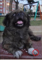
![x]() direction. For instance, consider the input image:
direction. For instance, consider the input image:![Original test image]()
observe how the red circle changes positions with respect to x (considering
![x]() the horizontal direction):
the horizontal direction):![Original test image]()
In OpenCV, the function remap offers a simple remapping implementation.
 as:
as:
 is the remapped image,
  the source image and
  is the mapping function that operates on
  and, say, we want to do a remap such that:
 direction. For instance, consider the input image:
Code
- What does this program do?
- Loads an image
- Each second, apply 1 of 4 different remapping processes to the image and display them indefinitely in a window.
- Wait for the user to exit the program
- The tutorial code’s is shown lines below. You can also download it from here
Explanation
Create some variables we will use:
Load an image:
Create the destination image and the two mapping matrices (for x and y )
Create a window to display results
Establish a loop. Each 1000 ms we update our mapping matrices (mat_x and mat_y) and apply them to our source image:
The function that applies the remapping is remap. We give the following arguments:
- src: Source image
- dst: Destination image of same size as src
- map_x: The mapping function in the x direction. It is equivalent to the first component of
![h(i,j)]()
- map_y: Same as above, but in y direction. Note that map_y and map_x are both of the same size as src
- CV_INTER_LINEAR: The type of interpolation to use for non-integer pixels. This is by default.
- BORDER_CONSTANT: Default
How do we update our mapping matrices mat_x and mat_y? Go on reading:
Updating the mapping matrices: We are going to perform 4 different mappings:
Reduce the picture to half its size and will display it in the middle:
![h(i,j) = ( 2*i - src.cols/2 + 0.5, 2*j - src.rows/2 + 0.5)]()
for all pairs
![(i,j)]() such that:
such that: ![\dfrac{src.cols}{4}<i<\dfrac{3 \cdot src.cols}{4}]() and
and ![\dfrac{src.rows}{4}<j<\dfrac{3 \cdot src.rows}{4}]()
Turn the image upside down:
![h( i, j ) = (i, src.rows - j)]()
Reflect the image from left to right:
![h(i,j) = ( src.cols - i, j )]()
Combination of b and c:
![h(i,j) = ( src.cols - i, src.rows - j )]()


 such that:
  and
and 


This is expressed in the following snippet. Here, map_x represents the first coordinate of h(i,j) and map_y the second coordinate.
Result
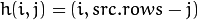
After compiling the code above, you can execute it giving as argument an image path. For instance, by using the following image:
![Original test image]()
This is the result of reducing it to half the size and centering it:
![Result 0 for remapping]()
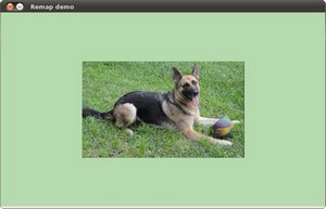
Turning it upside down:
![Result 0 for remapping]()
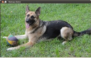
Reflecting it in the x direction:
![Result 0 for remapping]()
Reflecting it in both directions:


↧
K-3D
LINK: http://www.k-3d.org/wiki/Main_Page
![]()
|
About K-3D
|
Using K-3D
|
Contributing to K-3D
|
|
K-3D News

 K-3D Joins Software Freedom Conservancy Google Summer of Code 2008 Report Mac OSX Installer Released! K-3D 0.7 Released! Keep in Touch |
↧
投影与相机空间
↧
↧
OpenGL学习脚印: 投影矩阵和视口变换矩阵(math-projection and viewport matrix)
↧
AUTOCAD二次开发工具
↧
Coding for Gestures and Flicks on Tablet PC running Vista
LINK: http://www.therobotgeek.net/articles/gestureblocks.aspx
![]()
For this article, I wanted to demonstrate how to access gestures and flicks using C# code. I'll talk about accessing flicks using the tablet API and accessing gestures using the N-Trig native libraries. Surprisingly I couldn't find much out there that goes into any kind of depth in coding for either of these topics. So it seemed like a good opportunity to present some examples. I've included code for a C# game that uses the gestures for control. I hope you find it fun and useful.
Even though they are called "flicks", a flick is really a single touch gesture and an N-Trig gesture is a double touch gesture. All the examples run on Windows Vista Ultimate 32bit. Windows Vista will only detect up to two fingers on the touch surface. However, Windows 7 promises to allow more than two finger detection. I'll have to try that next. HP is already shipping hardware that is multi-touch enabled on their TouchSmart PCs. The Dell Latitude XT and XT2 tablet PCs are also using the N-Trig hardware for multi-touch.
Code to Detect If Running on a Tablet PC
I found some simple code to determine if your app is running on a tablet PC. It is a native call to GetSystemMetrics which is in User32.dll and you pass in SM_TABLETPC. I've included this code in the Flicks class. You may want your app to auto-detect if it's running on a tablet to determine which features to enable.
[DllImport("User32.dll", CharSet = CharSet.Auto)]
public static extern int GetSystemMetrics(int nIndex);
public static bool IsTabletPC()
{
int nResult = GetSystemMetrics(SM_TABLETPC);
if (nResult != 0)
return true;
return false;
}
Accessing Flicks (Single Touch Gestures) or UniGesture
If you've never heard of flicks before, they are single touch gestures that are triggered based on the speed of the touch across the tablet surface. You can find more detail here. It currently gives you eight directions that can be programmed at the OS level for use by applications.
I used the tabflicks.h file that I found in the folder - "C:\Program Files\Microsoft SDKs\Windows\v6.0A\Include" This header file is included with the Windows SDK. It contains all the flick structures and macro definitions needed to access flicks. I created a class library project called FlickLib that contains the C# structures, DllImports and code to store and process the data. I also wrote a test WinForm application that shows the usage of the library.
97
98 /// <summary>
99 /// Override the WndProc method to capture the tablet flick messages
100 /// </summary>
101 /// <param name="msg"></param>
102 protected override void WndProc(ref Message msg)
103 {
104 try
105 {
106 if (msg.Msg == Flicks.WM_TABLET_FLICK)
107 {
108 Flick flick = Flicks.ProcessMessage(msg);
109 if (flick != null)
110 {
111 this.txtOutput.Text = string.Format("Point=({0},{1}) {2}\r\n",
112 flick.Point.X,
113 flick.Point.Y,
114 flick.Data.Direction);
115
116 // Set to zero to tell WndProc that message has been handled
117 msg.Result = IntPtr.Zero;
118 }
119 }
120
121 base.WndProc(ref msg);
122 }
123 catch (Exception ex)
124 {
125 this.txtOutput.Text += string.Format("{0}\r\n", ex.Message);
126 }
127 }
128
I override the WndProc method of the WinForm to gain access to the WM_TABLET_FLICK messages sent to the window. The flick data is encoded in the WParam and the LParam of the windows message. I discovered that even though the params are IntPtr type, they are not actually pointers but are the real integer values to be used. I kept getting an Access Violation exception when I was trying to marshal the IntPtr to a structure. The solution was non-obvious. I couldn't find that documented anywhere. But it works correctly now so this is my contribution to the web for anyone trying to solve the same problem.
It is important to note that on line # 117, I set msg.Result = IntPtr.Zero. This tells the base.WndProc method that the message has been handled so ignore it. This is important because the underlying pen flicks can be assigned to actions such as copy and paste. If the message is not flagged as handled, the app will attempt to perform the action.
WinForm Flicks Test C# source code WinFlickTest.zipAccessing Double Touch Gestures or DuoGestures
The N-Trig hardware on the HP TouchSmart tablet provides the ability to detect two (or more) touches on the surface. This allows the tablet to respond on two finger gestures. You can see the current DuoGestures in use from N-Trig here.
I've created a class library project called GestureLib which wraps the native libraries from N-Trig so that they can be called using C#. Obviously this will only run on tablets that have the N-Trig hardware. Currently there is the HP TouchSmart tx2 and the Dell Latitude XT & XT2 laptops. I'll be testing and updating code for the HP TouchSmart IQ505 panel that uses the NextWindow hardware. If someone has any other tablets, touch panels and/or UMPC devices, I'd be happy to work together to create a version for that as well.
private Gestures _myGestures = new Gestures();
private int NTR_WM_GESTURE = 0;
/// <summary>
/// Override OnLoad method to Connect to N-Trig hardware and
/// Register which gestures you want to receive messages for and
/// Register to receive the Window messages in this WinForm
/// </summary>
/// <param name="eventArgs"></param>
protected override void OnLoad(EventArgs eventArgs)
{
try
{
bool bIsConnected = this._myGestures.Connect();
if (bIsConnected == true)
{
this.txtOutput.Text += "Connected to DuoSense\r\n";
TNtrGestures regGestures = new TNtrGestures();
regGestures.ReceiveRotate = true;
regGestures.UseUserRotateSettings = true;
regGestures.ReceiveFingersDoubleTap = true;
regGestures.UseUserFingersDoubleTapSettings = true;
regGestures.ReceiveZoom = true;
regGestures.UseUserZoomSettings = true;
regGestures.ReceiveScroll = true;
regGestures.UseUserScrollSettings = true;
bool bRegister = this._myGestures.RegisterGestures(this.Handle, regGestures);
if (bRegister == true)
{
this.NTR_WM_GESTURE = Gestures.RegisterGestureWinMessage();
if (this.NTR_WM_GESTURE != 0)
this.txtOutput.Text += string.Format("NTR_WM_GESTURE = {0}\r\n", this.NTR_WM_GESTURE);
}
}
else
this.txtOutput.Text = "Error connecting to DuoSense\r\n";
}
catch (Exception ex)
{
this.txtOutput.Text += string.Format("{0}\r\n", ex.Message);
}
}
/// <summary>
/// Override OnClosing method to ensure that we Disconnect from N-Trig hardware
/// </summary>
/// <param name="cancelEventArgs"></param>
protected override void OnClosing(CancelEventArgs cancelEventArgs)
{
this._myGestures.Disconnect();
base.OnClosing(cancelEventArgs);
}
Once you look at the code you will note that you have to connect to the N-Trig hardware at the start of the app. I put that call in the OnLoad method. Once you have a handle to the hardware, then you will use that throughout the lifetime of the app. It is stored in the Gestures class. With the handle, you will register which gesture messages you want the window to receive. Once registered, you will start to see NTR_WM_GESTURE message showing up in the WndProc method. I created a ProcessMessage method in the Gestures class that will determine which gesutre type it is and extract the data for the particular gesture.
One thing to note is if you look at the DllImports for the NtrigISV.dll native library you will see that there is name mangling with the method calls. I had to use Dependency Walker to determine the actual names of the methods. So be warned that when N-Trig releases a new version of their DLL that this code will probably break.
N-Trig Gestures WinForm Test source code WinGestureTest.zipProblems with Marshalling Data from C++ to C#
I had an issue where I was only getting the Zoom messages. My friend, Ben Gavin, helped me solve the problem. It had to do with marshalling the data into the struct. The original C++ struct looks like this:
typedef struct _TNtrGestures
{
bool ReceiveZoom;
bool UseUserZoomSettings;
bool ReceiveScroll;
bool UseUserScrollSettings;
bool ReceiveFingersDoubleTap;
bool UseUserFingersDoubleTapSettings;
bool ReceiveRotate;
bool UseUserRotateSettings;
} TNtrGestures;
For my original port, I just did a LayoutKind.Sequential and set everything as a bool like below.
[StructLayout(LayoutKind.Sequential)]
public struct TNtrGestures
{
public bool ReceiveZoom;
public bool UseUserZoomSettings;
public bool ReceiveScroll;
public bool UseUserScrollSettings;
public bool ReceiveFingersDoubleTap;
public bool UseUserFingersDoubleTapSettings;
public bool ReceiveRotate;
public bool UseUserRotateSettings;
}
Trouble is that bool in C++ is one byte where as a bool in C# is an Int32 or four bytes. Now if the C++ struct was labeled with a BOOL, then it would have been four bytes. So the new declaration of the struct in C# looks like this:
[StructLayout(LayoutKind.Explicit)]
public struct TNtrGestures
{
[FieldOffset(0)]public bool ReceiveZoom;
[FieldOffset(1)]public bool UseUserZoomSettings;
[FieldOffset(2)]public bool ReceiveScroll;
[FieldOffset(3)]public bool UseUserScrollSettings;
[FieldOffset(4)]public bool ReceiveFingersDoubleTap;
[FieldOffset(5)]public bool UseUserFingersDoubleTapSettings;
[FieldOffset(6)]public bool ReceiveRotate;
[FieldOffset(7)]public bool UseUserRotateSettings;
}
Once I used the FieldOffsetAttribute to set each bool to one byte each, the Rotate messages started to work correctly. Thanks Ben...
WPF Gestures Example Code
WindowInteropHelper winHelper = new WindowInteropHelper(this);
HwndSource hwnd = HwndSource.FromHwnd(winHelper.Handle);
hwnd.AddHook(new HwndSourceHook(this.MessageProc));
Using the same GestureLib class library, I also created an app that shows how to capture the gestures using a WPF application. That was an interesting exercise because I had never gotten a Windows handle from a WPF app. I discovered the WinInteropHelper class that gets the underlying Windows handle. I also had to hook the MessageProc handler to get the messages. The WndProc method is not available to override in WPF.
WPF Gestures Test source code WpfGestureTest.zipGesture Blocks - C# Game using Gestures and Flicks
Just creating test apps is boring and I wanted to create a game example that uses the flicks and gestures for control. I chose to build a simple game that shows off some of the possibilities for touch control. I call the game Gesture Blocks. It will give you a good starting point on using gestures in games. Watch the video to see the gestures in action.
Gesture Blocks Game source code WinGestureBlocks.zipConclusion
I hope the code I provided was useful and helpful. I will try to update the examples as issues are resolved. I'm also going to work on some other game examples that continue to show what can be done with gestures. The next project will be to load Windows 7 onto the tablet and write some code for more than DuoGestures.
↧
NextWindow Two-Touch API
LINK: http://www.nextwindow.com/support/application_notes/api.html
http://www.touchsmartcommunity.com/forum/thread/198/Multitouch-on-Touch-Smart/
![]()
http://www.touchsmartcommunity.com/forum/thread/198/Multitouch-on-Touch-Smart/
NextWindow's touch Application Program Interface (API) provides programmers with access to touch data generated by a NextWindow touch screen. It also provides derived touch information. For information about the capabilities of NextWindow products and which ones you can interface to using the API, see NextWindow Latest Technical Information.
The touch events, data and derived information can be used in any way the application wants.
Communications are via HID-compliant USB.
The API is in the form of a DLL that provides useful functions for application developers.
Multi-Touch
Multi-touch simply refers to a touch-sensitive device that can independently detect and optionally resolve the position of two or more touches on screen at the same time. In contrast, a traditional touch screen senses the position of a single touch and hence is not a multi-touch device.
 |
“Detect” refers to the ability to sense that a touch has occurred somewhere on screen. |
|
“Resolve” refers to the ability to report the coordinates of the touch position. |
NextWindow’s standard optical touch hardware can detect two touches on screen. The firmware can resolve the position of two simultaneous touches (with some limitations).
NextWindow Multi-Touch API Downloads
NWMultiTouchAPI_v1260.zip contains the following files:
| NWMultiTouch.dll | The DLL file containing the Multi-Touch API. |
| NWMultiTouch.h | The Header file containing the function definitions. |
| NWMultiTouchMS.lib | The Library file for Microsoft Visual Studio compiler |
| NWMultiTouch.lib | The Library file for Borland and other compilers |
Note
NextWindow's DLL is 32-bit. If you are building an application on a 64-bit machine, you need to specify a 32-bit build. To change this setting in Visual C#, change the platform target to x86 under the Build page of Project Settings. See the following Microsoft article for more details.
http://msdn.microsoft.com/en-us/library/kb4wyys2.aspx
Example Code
NWMultiTouchCSharpSample_v1260.zip
NWMultiTouchCPlusPlusSample_v1260.zip
Documentation
NextWindow USB API User Guide v1.7 (91 KB pdf file)
NextWindow Multi-Touch Whitepaper (2722 KB pdf)
↧
↧
Multi-Touch Systems that I Have Known and Loved
↧
An HP TouchSmart Application Development Guidelines Primer (Page 1 of 3)
LINK: http://www.touchsmartcommunity.com/article/95/An-HP-TouchSmart-Application-Development-Guidelines-Primer/
![]()
An introduction to building HP TouchSmart-hosted applications and a step-by-step tutorial for a “Hello World”
Building Your First TouchSmart Application
A developers guide to the TouchSmart Platform
Introduction
The Hewlett-Packard TouchSmart PC is an innovative new PC form-factor which affords users the unique ability to control interactions using only their hands. Through the use of a very stylish “10 foot” style user interface, the user can simply touch the integrated screen and perform most essential functions – viewing photos, listening to music, and surfing the web – all without using a keyboard or mouse.
The TouchSmart interface can be considered an entirely new user-interface platform – and now HP has opened up this platform to the entire developer community. With the release of the TouchSmart Application Developer Guidelines you can now build applications which run on this unique platform – and cater to its expanding user-base.
This article walks you through building your first TouchSmart application, with the goal of creating a basic application template which you can use for all your TouchSmart projects.
Getting Started
In order to follow the steps in this document, you will need to be familiar with Windows Presentation Foundation (WPF) and .NET development with C#. This article assumes a basic knowledge of these technologies. Please visit the Microsoft Developer Network (MSDN) at http://msdn.microsoft.com for more information.
In addition, the following is required:
- TouchSmart PC (model IQ504 or IQ506, current at the time of this writing)
- Latest TouchSmart software (available from http://support.hp.com)
- Microsoft Visual Studio 2008, Express (free) or Professional Edition
- HP TouchSmart Application Development Guidelines (available from here).
- .NET Framework 3.5 (although the same techniques can be used to build an application using Visual Studio 2005 and .NET 3.0)
It is recommended you install Visual Studio 2008 on the TouchSmart PC for ease of development, however it is not required. Since the TouchSmart application we are building is simply a Windows Presentation Foundation application it will run on any Vista or Windows XP PC with .NET 3.5.
Important Background Information
Before getting started you should know some important background information about a typical TouchSmart application:
- To best integrate with the TouchSmart look-and-feel you should develop your application using the Windows Presentation Foundation (WPF)
- The application runs as a separate process with a window that has the frame removed, it is not running within the TouchSmart shell process.
- The TouchSmart shell is responsible for launching your application. Additionally, the TouchSmart shell will control the position and sizing of your window.
- You must create three separate UI layouts for your application. This is not as difficult as it sounds; only one layout is interactive with controls – the other two layouts are for display only.
- Design your application for a “10 foot” viewing experience. Plan to increase font and control sizes if you are converting an existing application.
- Do not use pop-up windows in your application. This is perhaps the most unique requirement in building a TouchSmart application. The Windows “MessageBox” and other pop-up windows are not supported and should not be used. The best model to follow is to build your application like it was going to run in a web browser.
- Your application must support 64-bit Vista, as this is the operating system used on the TouchSmart PC.
Building the HelloTouchSmart Application
The rest of this article describes how to build a basic TouchSmart enabled application. Over the next few sections, you will build a basic TouchSmart application which you can use as a template for all your TouchSmart projects.
Start by launching Visual Studio 2008 and create a new project. If you have User Account Control (UAC) enabled make sure to launch Visual Studio with Administrator privileges.
- On the File menu, select New Project
- Select WPF Application
- Name your project “HelloTouchSmart” and click OK
- For Visual Studio 2008 Professional Users, select the path to save your project. Choose “C:\TouchSmart”
- For Visual Studio 2008 Express users, you will be prompted to save when you close your project. Choose “C:\TouchSmart” as the path to save your project to.
1. After the project is created, double-click the Window1.xaml file to open it. You are now going to make some important changes to this file which make it a TouchSmart application:
- Edit the Window definition to match the XAML below. The most important aspect of this is making your application appear without a Window frame (using the combination of ShowInTaskbar, WindowStyle, and ResizeMode attributes). Additionally, it is important to position your window off screen (using the Top and Left attributes), since the TouchSmart shell will move it into the correct position as needed.
<Window xmlns="http://schemas.microsoft.com/winfx/2006/xaml/presentation" xmlns:x="http://schemas.microsoft.com/winfx/2006/xaml" Name="HelloTouchSmart" Top="{Binding Source={x:Static SystemParameters.VirtualScreenHeight}}" Left="{Binding Source={x:Static SystemParameters.VirtualScreenWidth}}" Background="Black" ShowInTaskbar="False" WindowStyle="None" ResizeMode="NoResize"> - Now add some basic text to the window by inserting the following between the elements in the XAML file. Keep in mind text on a TouchSmart UI should be large (at least 18 point), and match the font family used by the TouchSmart shell.
<TextBlock Text="My first TouchSmart App!" Foreground="White" FontFamily="Segoe UI" FontSize="24"/>
2. Select Build, then Build Solution to create the HelloTouchSmart application.
- Depending on the edition of Visual Studio you are using, the “HelloTouchSmart.exe” will be created in either the bin\Debug (Visual Studio Professional) or bin\Release (Visual Studio Express) folders
- It is important to know where the output file is located since we will be registering the application with the TouchSmart shell in the next step.
3. Create a new XML file which contains information to register the application with the TouchSmart shell
- Select Project then Add New Item
- Select XML File
- Create a file called Register.xml
4. The registration XML file needs specific attributes including the full-path to your application. Replace the contents of the file you created in the previous step with the contents below. If you have created your project in a different path make sure you correct the AppPath element below.
<AppManagementSetting>
<UserEditable>true</UserEditable>
<RunAtStartup>true</RunAtStartup>
<RemoveFromTaskbar>false</RemoveFromTaskbar>   <AppPath>C:\TouchSmart\HelloTouchSmart\HelloTouchSmart\bin\Release\HelloTouchSmart.exe
</AppPath>
<AppParameters>chromeless</AppParameters>
<AllowAttach>true</AllowAttach>
<Section>Top</Section>
<Type>InfoView</Type>
<DisplayName>HelloTouchSmart</DisplayName>
<IsVisible>true</IsVisible>
<UserDeleted>false</UserDeleted>
<InDefaultSet>false</InDefaultSet>
<IconName />
</AppManagementSetting>
5. Save the XML file. Now it will need to be registered with the TouchSmart shell for your application to start appear in the TouchSmart shell.
- Make sure the TouchSmart shell is completely closed (click Close from the TouchSmart shell main screen)
- Start a command window with Admin rights (if UAC is enabled)
- Change the working directory to C:\Program Files(x86)\Hewlett-Packard\TouchSmart\SmartCenter 2.0
- Type the following command line to register your application RegisterSmartCenterApp.exe updateconfig “C:\TouchSmart\HelloTouchSmart\HelloTouchSmart\Register.xml”
- You should receive a successful message upon installation. Note you only need to register your application once.
6. After finishing these steps you should be greeted with your first TouchSmart application. Congratulations!

Enhancing the HelloTouchSmart Application
Now that you have a basic idea of how to build a TouchSmart application, the next step is to enhance it take advantage of the three layouts in the TouchSmart shell.
Each TouchSmart application needs to support three different UI views: small, medium, and large. If the user drags an application from the bottom area to the top area, it should switch from a small layout to a medium layout. If the user then clicks on the application in the medium layout it should switch to a large layout.
The small layout typically is an image that represents your application. The artwork should be a high-quality image that blends into the TouchSmart shell as best as possible.
The medium layout typically represents a non-interactive status view of your application. If your application is designed to display content from the web, for instance, this could be recent information your application has downloaded (e.g. most recent photos).
Finally, the large view represents your application. This is where you should expose all functions and features you intend to provide to the user. In the steps below we will enhance our sample to display an icon in the small layout and two different layouts for the medium and large views.
1. Start by closing the TouchSmart shell completely (clicking the Close button in the lower right-hand corner). Currently you will also need to manually “end task” the “HelloTouchSmart.exe” from the Windows task manager, as it doesn’t get closed by the TouchSmart shell when you close it. If you don’t close the application Visual Studio will be unable to build your project.
2. Open the HelloTouchSmart project
- Double-click on the Window1.xaml file to open it. First we are going to define the 3 UI layouts.
- We will also need an image in the project. Copy your favorite image (here we copied img35.jpg from the \Windows\Web\Wallpaper folder which is present on every installation of Windows Vista) into the project folder.
- Add the image to your project by selecting Project->Add Existing Item. Change the file filter to “Image Files” then select the image file from your project folder.
3. You can define your layout using any of the WPF container elements; however for this example we are going to use the DockPanel.
- Remove the TextBlock we defined in the section above.
- Define three new sections between the as follows:
<DockPanel Name="SmallUI" Background="Black">
    <Image Stretch="UniformToFill" Source="img35.jpg"/>
    </DockPanel>
    <DockPanel Name="MediumUI" Background="Black">
    <TextBlock Text="Medium UI" Foreground="White" FontFamily="Segoe UI"
    FontSize="24"/>
    </DockPanel>
    <DockPanel Name="LargeUI" Background="Black">
    <TextBlock Text="Large UI" Foreground="White" FontFamily="Segoe UI"
    FontSize="96"/>
    </DockPanel>
4. Compile the application then launch the TouchSmart shell.
- There may be cases where the TouchSmart shell won’t re-launch your application properly.
- If your application doesn’t appear for any reason (or appears without a UI), click Personalize, find the HelloTouchSmart tile, de-activate it and click OK.
- Click Personalize again, find the HelloTouchSmart tile, activate it and click OK.
- The TouchSmart shell should now launch your application.
![]()

5. As you can see our application appears but is only showing the large view. Close the TouchSmart shell and switch back to Visual Studio – we’ll fix this issue now.
- Remember to “end task” HelloTouchSmart.exe from the Windows task manager
6. We are now going to add some code to Window1.xaml.cs to handle the resizing and show the appropriate controls.
- Double-click on the Window1.xaml.cs file to open it. We will add code to show and hide our three DockPanels based on the size of the UI.
- The size ratios below were derived from the HP TouchSmart Application Development Guidelines.
public Window1() { InitializeComponent(); SizeChanged += new SizeChangedEventHandler(Window1_SizeChanged); } void Window1_SizeChanged(object sender, SizeChangedEventArgs e) { double ratio = Math.Max(this.ActualWidth, this.ActualHeight) / Math.Max(SystemParameters.PrimaryScreenWidth, SystemParameters.PrimaryScreenHeight); if (ratio >= 0.68295) //Large { SmallUI.Visibility = Visibility.Collapsed; MediumUI.Visibility = Visibility.Collapsed; LargeUI.Visibility = Visibility.Visible; } else if (ratio <= 0.18) //Small { SmallUI.Visibility = Visibility.Visible; MediumUI.Visibility = Visibility.Collapsed; LargeUI.Visibility = Visibility.Collapsed; } else //Medium { SmallUI.Visibility = Visibility.Collapsed; MediumUI.Visibility = Visibility.Visible; LargeUI.Visibility = Visibility.Collapsed; } } - Seasoned WPF developers might see a better way to hide/show the panels but for the sake of being clear and concise we are keeping this code fairly simple. Feel free to create your own mechanism that suits your particular need.
- Since the TouchSmart shell simply resizes and positions your window according to its needs you can use any WPF standard event handling and perform necessary adjustments to your user interface.
7. One final change is to prevent the application from being accidentally launched by a user. Since the application’s window appears initially off-screen it is important we only allow the application to be started by the TouchSmart shell.
- Change the Window1 constructor to the following:
public Window1() { bool okToRun = false; foreach (string str in Environment.GetCommandLineArgs()) { if (str.CompareTo("chromeless") == 0) { okToRun = true; } } if (!okToRun) { Application.Current.Shutdown(); } else { InitializeComponent(); SizeChanged += new SizeChangedEventHandler(Window1_SizeChanged); } } - The parameter being checked (chromeless) was actually provided in the registration XML file created in the first part of this article. The TouchSmart shell will pass this parameter to your application on launch.
8. Compile and run your application as done in step four. You should now see your application display three distinct user interfaces depending on its placement in the TouchSmart shell.

You might have noticed the application at this point does not have an icon in the shell. To fix this issue create a compressed “Windows Vista style”256x256 PNG icon and embed it in the application executable by selecting Project->Properties and select your icon from the Application tab. There are several 3rd party tools for creating this specialized type of icon available since the standard version of Visual Studio does not support compressed PNG icons.
Tips for Debugging
If you would like to debug your application with the Visual Studio debugger we recommend you attach to the running process by selecting Debug->Attach to Process. This only works for the Professional Edition of Visual Studio.
To debug with the Express edition, you must change your window style to run as a normal Windows application and remove the check for “chromeless” above.
Summary
You should now be familiar with how a basic TouchSmart application is put together and have a good starting point for your future projects. Some other important items not covered (but are outlined in the HP TouchSmart Application Development Guidelines) include application skinning and UI notifications. These advanced topics will be covered in a follow-up article, however for now please refer to the HP developer document for more detailed information.
↧
Maths - Angle between vectors
LINK: http://www.euclideanspace.com/maths/algebra/vectors/angleBetween/index.htm
![]()
How do we calculate the angle between two vectors?
For 2D Vectors
This is relatively simple because there is only one degree of freedom for 2D rotations. If v1 and v2 are normalised so that |v1|=|v2|=1, then,
angle = acos(v1•v2)
where:
- • = 'dot' product (see box on right of page).
- acos = arc cos = inverse of cosine function see trigonometry page.
- |v1|= magnitude of v1.
The only problem is, this won't give all possible values between 0° and 360°, or -180° and +180°. In other words, it won't tell us if v1 is ahead or behind v2, to go from v1 to v2 is the opposite direction from v2 to v1.
In most math libraries acos will usually return a value between 0 and PI (in radians) which is 0° and 180°.
If we want a + or - value to indicate which vector is ahead, then we probably need to use the atan2 function (as explained on this page). using:
angle of 2 relative to 1= atan2(v2.y,v2.x) - atan2(v1.y,v1.x)
For 3D Vectors
Axis Angle Result
This is easiest to calculate using axis-angle representation because:
- the angle is given by acos of the dot product of the two (normalised) vectors: v1•v2 = |v1||v2| cos(angle)
- the axis is given by the cross product of the two vectors, the length of this axis is given by |v1 x v2| = |v1||v2| sin(angle).
this is taken from this discussion.
So, if v1 and v2 are normalised so that |v1|=|v2|=1, then,
angle = acos(v1•v2)
axis = norm(v1 x v2)
If the vectors are parallel (angle = 0 or 180 degrees) then the length of v1 x v2 will be zero because sin(0)=sin(180)=0. In the zero case the axis does not matter and can be anything because there is no rotation round it. In the 180 degree case the axis can be anything at 90 degrees to the vectors so there is a whole range of possible axies.
| angle (degrees) | sin(angle) | cos(angle) | v1•v2 | v1 x v2 |
| 0 | 0 | 1 | 1 | 0,0,0 |
| 90 | 1 | 0 | 0 | unit len |
| 180 | 0 | -1 | -1 | 0,0,0 |
| 270 | -1 | 0 | 0 | unit len |
Quaternion Result
One approach might be to define a quaternion which, when multiplied by a vector, rotates it:
p2=q * p1
This almost works as explained on this page.
However, to rotate a vector, we must use this formula:
p2=q * p1 * conj(q)
where:
- p2 = is a vector representing a point after being rotated
- q = is a quaternion representing a rotation.
- p1= is a vector representing a point before being rotated
This is a bit messy to solve for q, I am therefore grateful to minorlogic for the following approach which converts the axis angle result to a quaternion:
The axis angle can be converted to a quaternion as follows, let x,y,z,w be elements of quaternion, these can be expressed in terms of axis angle as explained here.
angle = arcos(v1•v2/ |v1||v2|)
axis = norm(v1 x v2)
s = sin(angle/2)
x = axis.x *s
y = axis.y *s
z = axis.z *s
w = cos(angle/2)
We can use this half angle trig formula on this page: sin(angle/2) = 0.5 sin(angle) / cos(angle/2)
so substituting in quaternion formula gives:
s = 0.5 sin(angle) / cos(angle/2)
x = norm(v1 x v2).x *s
y = norm(v1 x v2).y *s
z = norm(v1 x v2).z *s
w = cos(angle/2)
multiply x,y,z and w by 2* cos(angle/2) (this will de normalise the quaternion but we can always normalise later)
x = norm(v1 x v2).x * sin(angle)
y = norm(v1 x v2).y * sin(angle)
z = norm(v1 x v2).z * sin(angle)
w = 2 * cos(angle/2) * cos(angle/2)
now substitute half angle trig formula on this page: cos(angle/2) = sqrt(0.5*(1 + cos (angle)))
x = norm(v1 x v2).x * sin(angle)
y = norm(v1 x v2).y * sin(angle)
z = norm(v1 x v2).z * sin(angle)
w = 1 + cos (angle)
because |v1 x v2| = |v1||v2| sin(angle) we can normalise (v1 x v2) by dividing it with sin(angle),
also apply v1•v2 = |v1||v2| cos(angle)so,
x = (v1 x v2).x / |v1||v2|
y = (v1 x v2).y/ |v1||v2|
z = (v1 x v2).z/ |v1||v2|
w = 1 + v1•v2 / |v1||v2|
If v1 and v2 are already normalised then |v1||v2|=1 so,
x = (v1 x v2).x
y = (v1 x v2).y
z = (v1 x v2).z
w = 1 + v1•v2
If v1 and v2 are not already normalised then multiply by |v1||v2| gives:
x = (v1 x v2).x
y = (v1 x v2).y
z = (v1 x v2).z
w = |v1||v2| + v1•v2
Matrix Result
Using the quaternion to matrix conversion here we get:
| 1 - 2*qy2 - 2*qz2 | 2*qx*qy - 2*qz*qw | 2*qx*qz + 2*qy*qw |
| 2*qx*qy + 2*qz*qw | 1 - 2*qx2 - 2*qz2 | 2*qy*qz - 2*qx*qw |
| 2*qx*qz - 2*qy*qw | 2*qy*qz + 2*qx*qw | 1 - 2*qx2 - 2*qy2 |
so substituting the quaternion results above into the matrix we get:
| 1 - 2*(v1 x v2).y2 - 2*(v1 x v2).z2 | 2*(v1 x v2).x*(v1 x v2).y - 2*(v1 x v2).z*(1 + v1•v2) | 2*(v1 x v2).x*(v1 x v2).z + 2*(v1 x v2).y*(1 + v1•v2) |
| 2*(v1 x v2).x*(v1 x v2).y + 2*(v1 x v2).z*(1 + v1•v2) | 1 - 2*(v1 x v2).x2 - 2*(v1 x v2).z2 | 2*(v1 x v2).y*(v1 x v2).z - 2*(v1 x v2).x*(1 + v1•v2) |
| 2*(v1 x v2).x*(v1 x v2).z - 2*(v1 x v2).y*(1 + v1•v2) | 2*(v1 x v2).y*(v1 x v2).z + 2*(v1 x v2).x*(1 + v1•v2) | 1 - 2*(v1 x v2).x2 - 2*(v1 x v2).y2 |
Substituting the following expansions:
(v1 x v2).x = v1.y * v2.z - v2.y * v1.z
(v1 x v2).y = v1.z * v2.x - v2.z * v1.x
(v1 x v2).z = v1.x * v2.y - v2.x * v1.y
(v1 x v2).x2 = v1.y * v2.z * v1.y * v2.z + v2.y * v1.z * v2.y * v1.z - 2 * v2.y * v1.z * v1.y * v2.z
(v1 x v2).y2 = v1.z * v2.x * v1.z * v2.x + v2.z * v1.x * v2.z * v1.x - 2* v2.z * v1.x * v1.z * v2.x
(v1 x v2).z2 = v1.x * v2.y * v1.x * v2.y +v2.x * v1.y * v2.x * v1.y - 2 * v2.x * v1.y * v1.x * v2.y
v1•v2 = v1.x * v2.x + v1.y * v2.y + v1.z * v2.z
This is getting far too complicated ! can anyone help me simplify this?
| Thank you again to minorlogic who gave me the following solution:
Hi ! you can use : And will get some thing : matrix33 RotAngonst vector3& from, const vector3& to ) vector3 v(vs); vector3 vt(v*(1.0f - ca)); matrix33 rotM; vt.x *= v.y; rotM.M12 = vt.x - vs.z; |
Code
axis-angle versionsfrotation angleBetween(sfvec3f v1,sfvec3f v2) {
float angle;
// turn vectors into unit vectors
n1 = v1.norm();
n2 = v2.norm();
angle = Math.acos( sfvec3f.dot(n1,n2) );
// if no noticable rotation is available return zero rotation
// this way we avoid Cross product artifacts
if( Math.abs(angle) < 0.0001 ) return new sfrotation( 0, 0, 1, 0 );
// in this case there are 2 lines on the same axis
if(Math.abs(angle)-Math.pi) < 0.001){
n1 = n1.Rotx( 0.5f );
// there are an infinite number of normals
// in this case. Anyone of these normals will be
// a valid rotation (180 degrees). so I rotate the curr axis by 0.5 radians this way we get one of these normals
}
sfvec3f axis = n1;
axis.cross(n2);
return new sfrotation(axis.x,axis.y,axis.z,angle);
}
quaternion version
/** note v1 and v2 dont have to be nomalised, thanks to minorlogic for telling me about this:
* http://www.euclideanspace.com/maths/algebra/vectors/angleBetween/minorlogic.htm
*/
sfquat angleBetween(sfvec3f v1,sfvec3f v2) {
float d = sfvec3f.dot(v1,v2);
sfvec3f axis = v1;
axis.cross(v2);
float qw = (float)Math.sqrt(v1.len_squared()*v2.len_squared()) + d;
if (qw < 0.0001) { // vectors are 180 degrees apart
return (new sfquat(0,-v1.z,v1.y,v1.x)).norm;
}
sfquat q= new sfquat(qw,axis.x,axis.y,axis.z);
return q.norm();
}
matrix version
sfmatrix angleBetween(sfvec3f v1,sfvec3f v2) {
// turn vectors into unit vectors
n1 = v1.norm();
n2 = v2.norm(); 	sfvec3f vs = new sfvec3f(n1);
vs.cross(n2); // axis multiplied by sin	sfvec3f v = new sfvec3f(vs);
v = v.norm(); // axis of rotation
float ca = dot(n1, n2) ; // cos angle	sfvec3f vt = new sfvec3f(v);	vt.scale((1.0f - ca);	sfmatrix rotM = new sfmatrix();
rotM.m11 = vt.x * v.x + ca;
rotM.m22 = vt.y * v.y + ca;
rotM.m33 = vt.z * v.z + ca;	vt.x *= v.y;
vt.z *= v.x;
vt.y *= v.z;	rotM.m12 = vt.x - vs.z;
rotM.m13 = vt.z + vs.y;
rotM.m21 = vt.x + vs.z;
rotM.m23 = vt.y - vs.x;
rotM.m31 = vt.z - vs.y;
rotM.m32 = vt.y + vs.x;
return rotM;
}
see also code from minorlogic
Vector Dot Product
The dot product operation multiplies two vectors to give a scalar number (not a vector).
It is defined as follows:
Ax * Bx + Ay * By + Az * Bz
This page explains this.
![]()
Vector Cross Product
The vector cross product gives a vector (or more strictly - a bivector) which is perpendicular to both the vectors being multiplied. The resulting vector A × B is defined by:
x = Ay * Bz - By * Az
y = Az * Bx - Bz * Ax
z = Ax * By - Bx * Ay
where x,y and z are the components of A × B
This page explains this.
Standards
Transforms
A transform maps every point in a vector space to a possibly different point.
When transforming a computer model we transform all the vertices.
To model this using mathematics we can use matrices, quaternions or other algebras which can represent multidimensional linear equations.
This page explains this.
Beginning Game Writing
↧
Project: Polygon Triangulation
LINK:http://www.mpi-inf.mpg.de/~kettner/courses/lib_design_03/proj/polygon_triang.html
Design the interface between data structures that represent simple polygons and generic algorithms that triangulate simple polygons.
The Standard Template Library (STL) [Austern98, SGI-STL] contains several examples of a similar interface design: Iterators are the interface between sequences of items in container classes and generic algorithms on sequences. However, they (usually) do not modify the container. Among the container classes some modifying functions, e.g., insert or remove, describe a standardized interface for modifying the container classes and can be used for generic algorithms on container classes. This project is expected to design a generic interface in the same spirit for triangulating polygons.
We start with a set of data structures that can represent a simple polygon, and with a set of algorithms that can triangulate it. We suggest to use the Computational Geometry Algorithms Library (CGAL) <www.cgal.org> [Fabri99] as a source of data structures and algorithms in geometry and also as a platform for realizing this project. Possible data structures could be:
- A
std::listof 2D points. - The class
CGAL::Polygon_2. - An individual facet of a 3D polyhedral surface, e.g., the class
CGAL::Polyhedron_3. - While working with the triangulation data structure underlying the class
CGAL::Triangulation_2one can end up in the situation to triangulate a polygonal hole in the triangulation structure.
All these representations would be for simple polygons without holes. An optional extension would be to extend this project to polygons with holes as they can be represented with:
- A
std::listofstd::list's of 2D points, where the first list is the outer boundary of the polygon and all succeeding lists are the inner boundaries of holes in the polygon, one list per hole. - The class
CGAL::Planar_map_2can contain faces with holes. - The class
CGAL::Nef_polyhedron_2can contain faces with holes.
Examples of algorithms that triangulate polygons are:
- Ear-cutting algorithm: An ear is a triangle formed by two consecutive edges of the polygon with a convex angle that contains no other point of a polygon. There exist always at least two ears in a polygon. An ear can be cut from the polygon, reducing its size and thus triangulating it.
- A sweep-line algorithm, see [Chapter 3, deBerg00].
- The constrained triangulation in CGAL. It creates a triangulation of the convex hull of a set of points respecting a set of constrained edges that have to be present in the triangulation, which would be the polygon boundary edges here. Afterwards the triangles in the polygon interior have to be selected, i.e., distinguished from those outside of the polygon.
Clearly iterators can be used in examining the input polygon. The new part will be the modifying part of the algorithms; where do we create and store the result triangles:
- For a single polygon we might just write triangles to an output iterator, for example, for storage in a container or for rendering.
- For polygons embedded in a data structure, such as a triangulation or a polyhedral surface, one wants the result triangles to replace the original polygon and to have the proper neighborhood pointers.
The goal of the project is to design the interface and to realize some of the data structures and algorithms, possibly based on the already existing CGAL implementations. The task includes:
- Analyse the set of operations of each agorithm and how it could be implemented for each data structure considered.
- Find a common set (or several sets) of operations that support the different combinations.
- Implement the interface for the data structures, possibly with adaptors for the existing data structures in CGAL.
- Implement the algorithm based on this interface, maybe also with adaptors to the already existing algorithms in CGAL.
- Test your generic algorithms on the different representations.
- Document the design, for example, in the style of CGAL or using Doxygen.
Prerequisites
This project requires interest in geometry or graphics and some knowledge of geometric algorithms. Since CGAL will be covered later in the course, it might be necessary to learn about CGAL prior to that.
References
- [Austern98]
- Mathew H. Austern. Generic Programming and the STL: Using and Extending the C++ Standard Template Library. Addison-Wesley, 1998.
- [SGI-STL]
- Silicon Graphics Computer Systems, Inc. Standard Template Library Programmer's Guide. http://www.sgi.com/tech/stl/.
- [Fabri99]
- Andreas Fabri, Geert-Jan Giezeman, Lutz Kettner, Stefan Schirra, and Sven Schönherr. On the Design of CGAL, the Computational Geometry Algorithms Library. Software -- Practice and Experience, submitted 1999, to appear. (also available as technical report)
- [deBerg00]
- Mark de Berg, Marc van Kreveld, Mark Overmars, and Otfried Schwarzkopf. Computational Geometry: Algorithms and Applications. Springer, 2nd edition, 2000.
- Mathew H. Austern. Generic Programming and the STL: Using and Extending the C++ Standard Template Library. Addison-Wesley, 1998.
↧
↧
K-3D
LINK: http://www.k-3d.org/wiki/Main_Page
![]()
|
About K-3D
|
Using K-3D
|
Contributing to K-3D
|
|
K-3D News
K-3D Joins Software Freedom Conservancy Google Summer of Code 2008 Report Mac OSX Installer Released! K-3D 0.7 Released! Keep in Touch |
↧
IDE Debug Helpers
https://wiki.qt.io/IDE_Debug_Helpers
Qt Creator
Qt Creator directly supports introspection of all Qt Containers and QObject derived classes for Qt 4 and Qt 5. User defined types can be supported in addition, see the Qt Creator documentation for details.
LLDB
There is an effort to introspect Qt types using LLDB at https://bitbucket.org/lukeworth/lldb-qt-formatters.
KDevelop ships formatter scripts in its LLDB plugin for Qt types that can be used directly in plain LLDB. https://unlimitedcodeworks.xyz/blog/2016/08/20/gsoc-kdevelop-lldb-final-report/#using-data-formatter-scripts-outside-kdevelop
MS visual studio QString & QByteArray expansions
The new layout of QString in Qt 5 is hard to inspect using the debugger. The following code can be added to autoexp.dat (c:\program files(x86)\visual studio 9.0\common7\packages\debugger\autoexp.dat) You should add it to the [Visualizer] section, before the STL/ATL containers.
; Qt types QStringData{ preview ([(unsigned short*)$e.d + $e.offset,su]) stringview ([(unsigned short*)$e.d + $e.offset,sub]) } QString{ preview ([$e.d]) } QByteArrayData{ preview ([(unsigned char*)$e.d + $e.offset,s]) stringview ([(unsigned char*)$e.d + $e.offset,sb]) } QByteArray{ preview ([$e.d]) } If all else fails you can always just add a watcher for
(char*)str.d + str.d->offset,su
in the debugger, to see the contents of str.
MS Visual Studio 2012
There is a new way to visualize native type, see http://code.msdn.microsoft.com/Writing-type-visualizers-2eae77a2 for details.
Ready-made .natvis files are included in the Visual Studio add-in.
So we can visualize QString and some other types using qt5.natvis file (save to file: %USERPROFILE%\Documents\Visual Studio 2012\Visualizers\qt5.natvis)
<?xml version="1.0" encoding="utf-8"?> <AutoVisualizer > <Type Name="QString"> <DisplayString>{(char*)d + d->offset,su}</DisplayString> </Type> <Type Name="QtPrivate::RefCount"> <DisplayString>{atomic}</DisplayString> </Type> <Type Name="QBasicAtomicInteger<int>"> <DisplayString>{_q_value}</DisplayString> </Type> <Type Name="QTypedArrayData<'''>"> <DisplayString>{{Count = {size}}}</DisplayString> <Expand> <Item Name="[size]">size</Item> <ArrayItems> <Size>size</Size> <ValuePointer>(iterator) ((char''')this + offset)</ValuePointer> </ArrayItems> </Expand> </Type> <Type Name="QByteArray"> <DisplayString>{*d}</DisplayString> </Type> <!— More Qt5 types… —> </AutoVisualizer> MS Visual Studio 2013
The ".natvis" files introduced in MSVS2012 received some additional attention in MSVS2013:
↧
放大鏡的原理
http://www.phy.ntnu.edu.tw/demolab/phpBB/viewtopic.php?topic=15841
http://enjoy.phy.ntnu.edu.tw/demolab/phpBB/
http://enjoy.phy.ntnu.edu.tw/demolab/phpBB/
| 光學 標題:放大鏡的原理 | |||
 1:黃福坤 (研究所)張貼:2006-10-22 12:39:58: 1:黃福坤 (研究所)張貼:2006-10-22 12:39:58: | |||
 上圖顯示眼睛直接觀看蜜蜂時在視網膜上呈現的大小,圖中 dn通常是明視距離也就是正常狀況為25cm. 視角= y0/dn 下圖則顯示使用放大鏡後的效果,視角=yi/L  比較兩圖可以知道 眼睛看物體的視角變大了! 兩者視角的放大比率就是 放大鏡的放大率(注意和一般透鏡放大率的定義M=-si/so=yi/yo不同) 放大鏡的放大率=(yi/L)/(yo/dn)=-si*dn/(so*L) 使用放大鏡時 物體通常非常接近焦距(si->L, so->f) 所以放大鏡的(角)放大倍率= dn/f 只和透鏡的焦距有關! | |||
| 2:黃福坤(研究所)張貼:2006-10-22 13:02:58: [回應上一篇] | |||
一旦你清楚瞭解了放大鏡的工作原理 之後要理解 望遠鏡或顯微鏡就很簡單了 放大鏡藉由將物體放在焦距內一點點 產生虛像的視角放大 讓眼睛看到更大的影像於視網膜上 若是有物體位於很遠的地方 我們知道 加上透鏡後物體會呈現於透鏡的焦點附近! 但是影像會很小 因此可以利用放大鏡的效果將其放大 若是我們在物體成像位置後放置另一個透鏡 且透鏡焦距就是該像與透鏡的距離(稍大一點) 於是 很遠處的物體所形成的像 被第二個透鏡以視角放大的方式讓我們看到 就是 望遠鏡了! 如下圖  而顯微鏡則是將物體放置於透鏡焦距到兩倍焦距之間,然後將所形成的像 再度透過第二個透鏡以放大鏡的方式放大 如下圖  | |||
| 3:吳旻峰榮譽點數5點 (高中職)張貼:2006-12-31 12:41:28: [回應上一篇] | |||
原來望遠鏡是兩個放大鏡,之前還認為是一個凸、ㄧ凹,幸好及時發現。 | |||
| 4:李偉榮譽點數3點(大學理工科系)張貼:2006-12-31 15:24:22: [回應上一篇] | |||
也有用一凸一凹做成的望遠鏡,例如從前在劇場使用的小型觀劇鏡。 | |||
| 5:吳旻峰榮譽點數5點 (高中職)張貼:2006-12-31 15:32:38: [回應上一篇] | |||
| 謝謝李偉老師及時的告知,原來原理就是用一個放大鏡來觀看凸透鏡或者凹面鏡所呈現的遠方物體影像,差一點變成另一種錯誤。 | |||
| 6:Adi (國中)張貼:2012-11-06 00:13:59: [回應第4篇] | |||
| 請問一凸一凹的望遠鏡如何劃成像圖 | |||
| 7:黃福坤(研究所)張貼:2012-11-06 19:45:40: [回應上一篇] | |||
| 一般的望遠鏡是用兩個凸透鏡組成 歡迎參考 凸透鏡成像與組合透鏡 (顯微鏡/望遠鏡) |
↧