|
||||||||||||||||||||||||||||||||||||
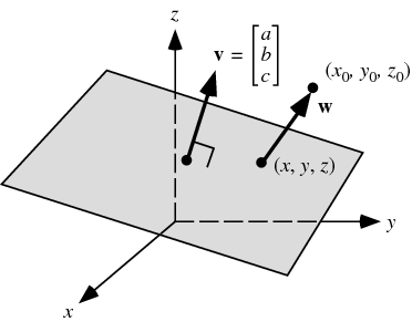 Given a plane
and a point
and a vector from the plane to the point is given by
Projecting
Dropping the absolute value signs gives the signed distance,
which is positive if This can be expressed particularly conveniently for a plane specified in Hessian normal form by the simple equation
where Given three points
Then the distance from a point
where
as it must since all points are in the same plane, although this is far from obvious based on the above vector equation.
Gellert, W.; Gottwald, S.; Hellwich, M.; Kästner, H.; and Künstner, H. (Eds.). VNR Concise Encyclopedia of Mathematics, 2nd ed. New York: Van Nostrand Reinhold, 1989.  CITE THIS AS: Weisstein, Eric W. "Point-Plane Distance." From MathWorld--A Wolfram Web Resource. http://mathworld.wolfram.com/Point-PlaneDistance.html |
Point-Plane Distance
BOOLEAN OPERATIONS
First, to explain the funny name : "It was named after George Boole, who first defined an algebraic system of logic in the mid 19th century."
Working in 3D usually involves the use of solid objects. At times you may need to combine multiple parts into one, or remove sections from a solid. AutoCAD has some commands that make this easy for you. These are the boolean operations as well as some other helpful commands for solids editing.:
The boolean commands work only on solids or regions. They are easy to work with IF you follow the command line prompts. Here is an example of each.
Start these exercises by drawing a box 5W X 7L X 3H and a cylinder 3 units in diameter so that the center of the circle is on the midpoint of the block.
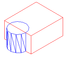
Below left, there is a box and a cylinder. These are two separate objects. If you want to combine them into one object, you have to use the union command.
 |
 |
|
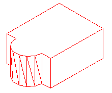
The UNION command combines one or more solid objects into one object. |
|
Here are the command line prompts and the resulting object:
Command: UNION <ENTER>
Select objects: <SELECT THE BLOCK> 1 found
Select objects: <SELECT THE CYLINDER> 1 found
Select objects: <ENTER>
NOTE: The object that you select first will determine the properties of the unioned object when it is created.
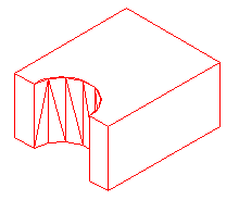
The subtract command is used to cut away, or remove the volume of one object from another. It is important to check the command line when using this command. Remember that AutoCAD always asks for the object that you are subtracting FROM first, then it asks for the objects to subtract. Here is an example:
 |
 |
|
The SUBTRACT command removes the volume of one or more solid objects from an object. |
|
Command: SUBTRACT
Select solids and regions to subtract from...
Select objects: <SELECT THE BLOCK> 1 found <ENTER>
Select objects: Select solids and regions to subtract...
Select objects: <SELECT THE CYLINDER> 1 found <ENTER>
Select objects: <ENTER>
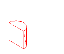
This command creates a new solid from the intersecting volume of two or more solids or regions. AutoCAD will find where the two objects have an volume of interference and retain that area and discard the rest. Here is an example of this command shown below:
 |
 |
|
The INTERSECT command combines the volume of one or more solid objects at the areas of interference to create one solid object. |
|
Command: INTERSECT
Select objects: <SELECT THE BLOCK> 1 found
Select objects: <SELECT THE CYLINDER> 1 found
Select objects: <ENTER>
Try these commands with various 3D solid objects to get familiar with them. Draw the block in Lesson 3-2. Draw the outline of the block, extrude it - then draw the circle and extrude it. Then subtract the circle from the block.
These commands will allow you do a lot of 3D work, using only the extrude and these boolean commands. Of course, there are some other ways to edit 3D solids.
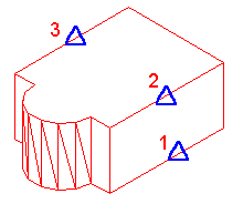
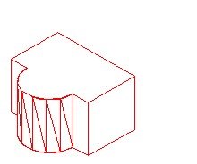
This command does exactly what the name implies. You can slice a 3D solid just like you were using a knife.
Start with the basic block and cylinder shape you used in the examples above.
 |
 |
|
The INTERSECT command combines the volume of one or more solid objects at the areas of interference to create one solid object. |
|
Command: SLICE
Select objects: 1 found
Select objects: Specify first point on slicing plane by
[Object/Zaxis/View/XY/YZ/ZX/3points] <3points>: PICK POINT 1
Specify second point on plane: PICK POINT 2
Specify third point on plane: PICK POINT 3
Specify a point on desired side of the plane or [keep Both sides]: <Pick on the side towards the cylinder>
This is a very useful command - think of it as a trim in 3D. Make sure you have your Osnaps on for this command and that you pick the correct points. In a complex 3D drawing, this can be tough to see.
Just as there is a "trim"-like command in 3D - there is also a "stretch". This is a new command in recent versions. 
I usually start this command by clicking on the menu item Modify > Solids Editing > Extrude Faces. There is also an icon for it on the Solids Editing menu.
The command is quite easy to use, but you need to be careful on which face you select.
Try to extend one edge of the block by 1 inch. Start the command and pick the face on the side (on the bottom line). You'll notice that the bottom face highlights as well. Next type R and pick the bottom face to remove it. Then follow the command line to finish the command.
Command: _solidedit
Solids editing automatic checking: SOLIDCHECK=1
Enter a solids editing option [Face/Edge/Body/Undo/eXit] <eXit>: _face
Enter a face editing option
[Extrude/Move/Rotate/Offset/Taper/Delete/Copy/coLor/Undo/eXit] <eXit>: _extrude
Select faces or [Undo/Remove]: (PICK BOTTOM LINE OF SIDE FACE) 2 faces found.
Select faces or [Undo/Remove/ALL]: R
Remove faces or [Undo/Add/ALL]: (PICK AN EDGE ON THE BOTTOM FACE)2 faces found, 1 removed.
Remove faces or [Undo/Add/ALL]: (ENTER)
Specify height of extrusion or [Path]: 1 (ENTER)
Specify angle of taper for extrusion <0>: (ENTER)
Solid validation started.
Solid validation completed.
Enter a face editing option
[Extrude/Move/Rotate/Offset/Taper/Delete/Copy/coLor/Undo/eXit] <eXit>: (ENTER)
You should end up with this:
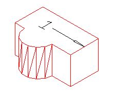
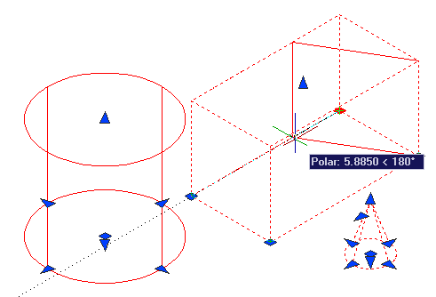
Another way of editing faces in AutoCAD 2007 is to use grips to extrude the faces, just like you would on a 2D object. Here is an image below that shows some of the grips available.This option is only available on the basic shapes shown in lesson 3-10.
Sometimes, you may find it faster or easier to draw something separately and then move and align it into place. The command to use this in 3D is (funnily enough) 3DALIGN.
This is a simple example, but will show you the method.
Draw a box that is 5 x 5 x 6 tall. Next draw a cylinder that is 3 in diameter and 1 tall. It should look like this:
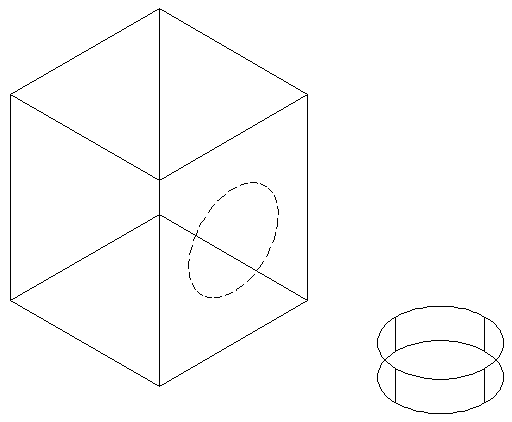
The goal will be to align the cylinder on the front face of the box where the dotted line is.
Turn on your quadrant Osnaps. Start the 3DALIGN command. You will first be asked to select the objects - select the cylinder and press enter.
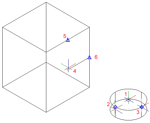
Now you will be asked to select the 3 points as indicated below: the centre and 2 quadrants. Now the cylinder will be "stuck" to your cursor as AutoCAD asks where it needs to go.
Line the cylinder up with the box by using object tracking to locate the centre of the face on the box first. Then pick on the midpoints to line up the cylinder to the box. After you pick the 3rd point, the cylinder should move into place and end the command.
Here's a view of the points that were picked incase you had trouble.
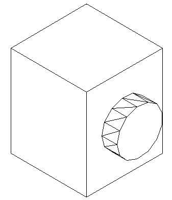
The finished 'alignment job' should look like this after using the hide command.
Review:
After learning how to draw some basic 3D solids, you can see that using equally basic editing commands you can have a lot of options. Before advancing, review these commands by drawing simple 3D shapes and editing them.
With the commands explained on these pages, you will be able draw most of the shapes you will need in 3D. There are other options, but get very familiar with these 3D editing options before moving on. The drawings done in the sample drawing section were done almost exclusively with the commands taught in Lessons 3-7 to 3-11. You approach will make the project easy or difficult. Think of the various ways to draw an object before starting. You could save days with some forethought.
Extra Practice: Draw this object as a 3D solid using primitive solids and boolean operations.
Extra Practice: Draw this object as a 3D solid using primitive solids and boolean operations.
GDAL API Tutorial
Touchlib Homepage

What is Touchlib?
Touchlib is our library for creating multi-touch interaction surfaces. It handles tracking blobs of infrared light for you and sends your programs multitouch events, such as 'finger down', 'finger moved', and 'finger released'. It includes a configuration app and a few demos to get you started. It interaces with most major types of webcams and video capture devices. It currently works only under windows but efforts are being made to port it to other platforms.
Who Should Use Touchlib?
Touchlib only comes with simple demo applications. If you want to use touchlib you must be prepared to make your own apps. There are a few ways to do this. You can build applications in C++ and take advantage of touchlib's simple programming interface. Touchlib does not provide you with any graphical or front end abilities - it simply passes you touch events. The graphics are up to you. If you like, take a look at the example apps which use OpenGL GLUT.
If you don't want to have to compile touchlib, binaries are available.
As of the current version, touchlib now can broadcast events in the TUIO protocol (which uses OSC). This makes touchlib compatible with several other applications that support this protocol, such as vvvv, Processing, PureData, etc.. This also makes it possible to use touchlib for blob detection / tracking and something like vvvv or Processing to write appliactions. Of course the other option is to do all your blob detection and processing in vvvv or processing. It's up to you. Supporting the TUIO protocol also enables a distributed architecture where one machine can be devoted to detection and tracking and another machine can handle the application.
If you don't like touchlib and want to program your own system, the latest version of OpenCV (1.0) now has support for blob detection and tracking. This might be a good starting point.
My Mindmap
My mindmap for the touchscreen is available here. This contains info on what parts you'll need for the construction of the screen, where to find them and some very basic instructions for how to build a screen. It also includes some more links. I hope it's useful for some of the people reading this who are interested in doing their own screens. You'll need Freemind (which is coincidentally, free), in order to view it. I'm a big fan of freemind for planning out projects and getting ideas down. It's hierarchical nature allows you to organize and hide parts you are not interested in. It can also link to images, other mindmaps and web pages.
FAQ
Frequently asked questions about the construction of the screen can be found here.
Where to get the source to Touchlib, our multitouch table library:
All our source code is available on our Google Code site at http://code.google.com/p/touchlib/ . You can acces the repsitory using Subversion. If you are using windows, get TortoiseSVN. Use Tortoise to access the repository and download all the files (much easier than going thru the web interface). If you are interested in porting touchlib to linux or the mac, please email me. The system was written in such a way that it should be easy to port and does not depend heavily on any windows specific api's.
Touchlib is written in C++ (the BlobTracking / Analysis is all written by yours truly) and has a Visual Studio 2005 Solution ready to compile. No docs are available right now and it's windows only (though it should be possible to make everything compile under other OS's with a little work). It currently depends on OpenCV, DirectShow (you'll need the Microsoft Platform SDK), VideoWrapper and the DSVideoLib. The source code includes our main library which you can link into your application to start capturing touch events. It has support for most major camera/webcam types. It also includes a basic config app which will need to be run in order to calibrate your camera, and has a couple example apps. Alternately, I've heard other people have used things like vvvv, EyesWeb, processing and Max/MSP in order to do blob tracking / processing and make applications. You can check out some of the demo apps if you want to see how it works. Pong or the config app should be fairly easy to follow. Setting up a bare minimum multitouch app should only take a dozen lines of code or less.
DL Links for dependencies:
- OpenCV - I used Beta 5. Hopefully it is compatible with newer versions (RC 1 is available now).
- DSVideoLib
- VideoWrapper
- Platform SDK
- Also GLUT was used for most of the applications.
- The DirectX SDK is also required
- OSCPack for the OSC application
You'll need to configure a few environment variables to get everything compiled. They are:
- DSVL_HOME - dsvideolib root directory
- VIDEOWRAPPER_HOME - root directory of the video wrapper library
- OPENCV_HOME - root directory of OpenCV
- OSCPACK_HOME - root directory of oscpack
The config app
In order to calibrate the touchlib library for your camera and projector, you'll need to run the config app. Here's how it works. You'll need to set up your computer so that the main monitor is the video projector so that the app comes up on that screen. Run the config app. Press 'b' at any time to recapture the background. Tweak the sliders until you get the desired results. The last step (rectify) should just have light coming from your finger tips (no background noise, etc). When you are satisfied press 'enter'. This will launch the app in full screen mode and you'll see a grid of points (green pluses). Now you can press 'c' to start calibrating. The current point should turn red. Press on your FTIR screen where the point is. Hopefully a press is detected (you can check by looking in the debug window). Press 'space' to calibrate the next point. You'll continue through until all points are calibrated. Note that the screen may not indicate where you are pressing. When you are all done, you can press 'ESC' to quit. All your changes (slider tweaks and calibration points) are saved to the config.xml file. Now when you run any touchlib app it will be calibrated. Note that any changes to where the projector is pointing or your webcam will require a re-calibration.
Testing
Alternate config files are available if you want to test the library using an .AVI for input (instead of the webcam). Replace the config.xml with 5point_avi.xml or 2point_avi.xml. You can edit those files to use a different AVI if you like (you can record a new one using your camera - but you may need to tweak some of the other settings in the config too).
Links
NEW: We now have an official community site for building FTIR tables. Access the site here . The site includes forums, a wiki, news and more.
Other tables and info.
- My Blog - read updates about my progress with the screen
- A HowTo for building FTIR screens
- Pasta and Vinegar: Interactive tables
- Reactivision software
- TUIO protocol
- Some nice info on the Tangent table.
- Links on del.icio.us tagged with multitouch
- DIY Multitouch - A bunch of links and info on various multitouch techniques.
- Khronos Projector - Uses infrared + a stretchy lycra surface and detects the depressions on the surface.
- Smartskin - uses capacitance testing to detect conductive objects, such as skin. Sounds like the best choice for a small form factor. Could fit over or be integrated with an LCD monitor.
- Malleable touch surface
- Here's one of the demos featured on Han's multitouch screen, in more detail. Rigid shape manipulation.
- Warcraft 3 multitouch. Nice. I'd like to be able to get this running on my screen (even if it's only single touch)
- this interesting item: the Entertaible
- Jeff Han's page. The one that started it all
Other
IRC: #ftir on irc.freenode.net
sparsh-ui

Project Goal
Iowa State University's Virtual Reality Applications Center (VRAC) is developing a multitouch API for enabling users to create multi-touch applications easily on a variety of hardware platforms. The API supports custom hardware drivers and is platform independent.
Project Components
Gesture Server: The Sparsh-UI Gesture Server is the main piece of the application. It handles gesture processing and passes touchpoints and/or gesture information to the client application. The Gesture Server supports basic gestures such as drag, scale, and rotate, and is extensible to support an infinite number of user-written custom gestures.
Input Device Driver: A device driver is needed for a device to communicate with the Gesture Server. The Touchtable team at VRAC has developed device drivers for an optical FTIR system, an infrared bezel, as well as several other devices. The driver should be capable of passing touchpoint iformation to the Gesture Server.
Gesture Adapter: A client adapter is needed for each GUI framework the Gesture Server intends to communicate with. The Touchtable team at VRAC is currently working on a Java Swing adapter, with plans to implement other frameworks in the near future.


Contact Information
For information about using Sparsh-UI, join our sparsh-ui developer group from the link on the right-hand side of this page, or contact Stephen Gilbert at (gilbert at iastate dot edu).
MultiTouch资料收集
0.不会飞的鱼 - 实战Multitouch(1)
http://isaaq.javaeye.com/blog/296853
1. (介绍后加)
http://link.brightcove.com/services/player/bcpid1875256036?bctid=20915830001
2. 超大型多点触摸墙,完美展示多点触摸的魅力
http://www.mt2a.com/viewthread.php?tid=70&extra=page%3D1
3. mt2a论坛
4. 一个OpenCV 机器视觉爱好者的blog
5. TouchLib 官方网站
6. DameTouch的视频空间(优酷)
7. 《世界构建者》(World Builder)
<embed src="http://player.youku.com/player.php/sid/XNzY0NjIyNDQ=/v.swf" quality="high" width="480" height="400" align="center" allowScriptAccess="sameDomain" type="application/x-shockwave-flash"></embed>
8. TouchLess 微软的无需接触的触摸技术
http://vimeo.com/1893407?pg=embed&sec=1893407
http://www.codeplex.com/touchless
9. 一种实现原理
Touchlib compiling instructions (Windows)
Hardware:
A webcam (USB or a Firewire)
Software:
Microsoft Visual Studio 2005
MS Visual Studio 2005
MS Visual Studio 2005 SP1
MS Visual Studio 2005 SP1 Update for Windows Vista (only needed when using vista)
TortoiseSVN
TortoiseSVN latest binaries
Miscallenous Libraries
OpenCV (download OpenCV_1.0.exe)
DSVideoLib (download dsvideolib-0.0.8c)
VideoWrapper (download VideoWraper_0.2.5.zip)
GLUT (download glut-3.7.6-bin.zip)
OSCpack (download oscpack_1_0_2.zip)
CMU 1394 Digital Camera Driver (download 1394camera645.exe)
Windows Server 2003 R2 SDK (aka Platform SDK) Web Install, Full download or ISO
The platform SDK has been replaced by the Windows SDK:
Download the Web Install or DVD ISO image
DirectX SDK (download August 2008 or newer)
Installation instructions
- First install Visual Studio 2005
- Install the the Visual Studio 2005 SP1 update - Vista users: Rightclick on the setup and run as administrator.
(Also be sure to have a few gigabytes spare on your C:\) - If you’re using Windows Vista you will need to install the SP1 update for Vista aswell, again in administrator mode.
(Windows XP users can continue reading). - Now it is time to install the libraries, start with installing OpenCV 1.0. Just use the recommend path and let it set the environment variables.
- Next, create a directory called C:\_libraries and unzip the content of dsvideolib, VideoWrapper, GLUT and OSCpack to this directory.
![touchlib1.jpg touchlib1.jpg]()
- Install the CMU 1394 Digital Camera Driver (yes, even if you dont have/use a firewire camera)
During the setup Check “Development Files” and “Program Shortcuts”. - Install the Platform SDK, typical settings should be fine.
(I used the ISO to install this, if you use the webinstaller be sure to download the right platform). - Install the DirectX SDK.
- Install TortoisSVN.
Setting environment variables
Depending on your setup you might need to change a few directory location values.
- Press the right mouse button on “My Computer” and choose: Properties > Advanced > Environmental Variables
- To add an entry, click “new” at the System Variables.
- Add the OpenCV root directory:
name: “OPENCV_HOME”
value: “C:\Program Files\OpenCV” - Add the DSVideoLib:
name: “DSVL_HOME”
value: “C:\_libraries\dsvl-0.0.8c” - Add the VideoWrapper
name: “VIDEOWRAPPER_HOME”
value: “C:\_libraries\VideoWraper_0.2.5″ - Add the OSCpack
name: “OSCPACK_HOME”
value: “C:\_libraries\oscpack_1_0_2\oscpack” - Add the CMU driver location
name: “CMU_PATH”
value: “C:\Program Files\CMU\1394Camera”
Checkout touchlib svn
- Create a directory called C:\multitouch in windows explorer
- Click the right mouse button and choose SVN Checkout
- Enter “http://touchlib.googlecode.com/svn/trunk/” as the URL of the repository
- Enter “C:\multitouch\touchlib” as checkout directory
- Click OK (confirm creation of the directory)
- Downloading the files might take a while because of the demo movies which are included. (rev. 395 is 121,14 MBytes)
Visual studio settings
We are almost done with setting up the enviroment, there are just a few steps left before we can compile Touchlib.
- Open up “solution.sln” in the “C:\multitouch\touchlib\build\VC8″ directory.
- Choose Tools > Options
- On the left choose Project and Solutions > VC++ Directories
- On the right change “Show directories for:” to “Include files”
- Add the directory “C:\Program Files\Microsoft SDKs\Windows\v6.1\Samples\Multimedia\DirectShow\BaseClasses”
- Add the directory “C:\Program Files\Microsoft SDKs\Windows\v6.1\Include”
- Add the directory “C:\Program Files\Microsoft DirectX SDK (March 2009)\Include”
- Add the directory “C:\_libraries\glut-3.7.6-bin”
- Change “Show directories for:” to “Library files”
- Add the directory “C:\Program Files\Microsoft SDKs\Windows\v6.1\Lib”
- Add the directory “C:\Program Files\Microsoft DirectX SDK (March 2009)\Lib\x86″
- Add the directory “C:\_libraries\glut-3.7.6-bin”
- Click OK
- In the menu choose Build > Build Touchlib
- When it has compiled Touchlib, Build > Build solution
- The End
![:)]()
* last update on 13-04-2009 (Latest windows sdk + dx sdk)
19 Responses to “Touchlib compiling instructions (Windows)”
Gesture recognition
Contents[hide] |
Background
Touchlib does a fine job of picking out contacts within the input surface. At the moment, there is no formal way of defining how those blob contacts are translated into intended user actions. Some of this requires application assistance to provide context, but some of it is down to pattern matching the appearance, movement and loss of individual blobs or combined blobs.
What I'm attempting to describe here, and for others to contribute to, is a way of
- Describing a standard library of gestures suitable for the majority of applications
- A library of code that supports the defined gestures, and generates events to the application layer
By using an XML dialect to describe gestures, it means that individual applications can specify their range of supported gestures to the Gesture Engine. Custom gestures can be supported.
By loosely coupling gesture recognition to the application, we can allow people to build different types of input device and plug them all into the same applications where appropriate.
In the early stages of development, we are all doing our own thing with minimal overlap. Over time we will realise the benefits of various approaches, and by using some standardised interfaces, we can mix and match to take advantage of the tools that work best for our applications. Hard coded interfaces or internal gesture recognition will tie you down and potentially make your application obsolete as things move on.
I'd really appreciate some feedback on this - this is just my take on how to move this forward a little at this stage.
Gesture Definition Markup Langauge
GDML is a proposed XML dialect that describes how events on the input surface are built up to create distinct gestures.
Tap Gesture
<gdml>
<gesture name="tap">
<comment>
A 'tap' is considered to be equivalent to the single click event in a
normal windows/mouse environment.
</comment>
<sequence>
<acquisition type="blob"/>
<update>
<range max="10" />
<size maxDiameter="10" />
<duration max="250" />
</update>
<loss>
<event name="tap">
<var name="x" />
<var name="y" />
<var name="size" />
</event>
</loss>
</sequence>
</gesture>
</gdml>
The gesture element defines the start of a gesture, and in this case gives it the name 'tap'.
The sequence element defines the start of a sequence of events that will be tracked. This gesture is considered valid whilst the events sequence remains valid.
The acquisition element defines that an acquisition event should be seen (fingerDown in Touchlib). This tag is designed to be extensible to input events other than blob, such as fiduciary markers, real world objects or perhaps facial recognition for input systems that are able to distinguish such features.
The update element defines the allowed parameters for the object once acquired. If the defined parameters become invalid during tracking of the gesture, the gesture is no longer valid.
The range element validates that the current X and Y coordinates of the object are within the specified distance of the original X and Y coordinates. range should ultimately support other validations, such as 'min'.
The size element validates that the object diameter is within the specified range. Again, min and other validations of size could be defined. Size allows you to distinguish between finger and palm sized touch events for example.
The duration element defines that the object should only exist for the specified time period (milliseconds). If the touch remains longer than this period, its not a 'tap', but perhaps a 'move' or 'hold' gesture.
The loss element defines what should occur when the object is lost from the input device.
The event element defines that the gesture library should generate a 'tap' event to the application layer, providing the x, y, and size variables.
Double Tap Gesture
<gesture name="doubleTap">
<comment>
A 'doubleTap' gesture is equivalent to the double click event in a normal
windows/mouse environment.
</comment>
<sequence>
<gestureRef id="A" name="tap" />
<duration max="250" />
<gestureRef id="B" name="tap">
<onEvent name="acquisition">
<range objects="A,B" max="10" />
</onEvent>
<onEvent name="tap">
<range objects="A,B" max="10" />
<event name="doubleTap">
<var name="x" />
<var name="y" />
<var name="size" />
</event>
</onEvent>
</gestureRef>
</sequence>
</gesture>
This example shows how more complex gestures can be built from simple gestures. A double tap gesture is in effect, two single taps with a short space between. The taps should be within a defined range of each other, so that they are not confused with taps in different regions of the display.
Note that the gesture is not considered invalid if a tap is generated in another area of the display. GestureLib will discard it and another tap within the permitted range will complete the sequence.
In the case of double tap, an initial tap gesture is captured. A timer is then evaluated, such that the gesture is no longer valid if the specified duration expires. However, if a second tap is initiated, it is checked to make sure that it is within range of the first. range is provided with references to the objects that need comparing (allowing for other more complex gestures to validate subcomponents of the gesture). This is done at the point of acquisition of the second object.
Once the second tap is complete and the event raised, range is again validated, and an event generated to inform the application of the gesture.
Move Gesture
<gesture name="move">
<comment>
A 'move' is considered to be a sustained finger down incorporating
movement away from the point of origin (with potential return during
the transition).
</comment>
<sequence>
<aquisition type="blob" />
<update>
<range min="5" />
<event name="move">
<var name="x" />
<var name="y" />
<var name="size" />
</event>
</update>
<loss>
<event name="moveComplete">
<var name="x" />
<var name="y" />
<var name="size" />
</event>
</loss>
</sequence>
</gesture>
Zoom Gesture
<gesture name="zoom">
<comment>
A 'zoom' is considered to be two objects that move towards or away from
each other in the same plane.
</comment>
<sequence>
<compound>
<gestureRef id="A" name="move">
<gestureRef id="B" name="move">
</compound>
<onEvent name="move">
<plane objects="A,B" maxVariance="5" />
<event name="zoom">
<var name="plane.distance" />
<var name="plane.centre" />
</event>
</onEvent>
<onEvent name="moveComplete">
<plane objects="A,B" maxVariance="5" />
<event name="zoomComplete">
<var name="plane.distance" />
<var name="plane.centre" />
</event>
</onEvent>
</sequence>
</gesture>
A zoom gesture is a compound of two move gestures.
The compound element defines that the events occur in parallel rather than series.
The plane element calculates the line between the two objects, and checks the maximum variance in the angle from its initial (so you can distinguish between a zoom and a rotate, for example).
'move' events from either object are translated into zoom events to the application.
Rotate Gesture
<gesture name="rotate">
<comment>
A 'rotate' is considered to be two objects moving around a central axis
</comment>
<sequence>
<compound>
<gestureRef id="A" name="move">
<gestureRef id="B" name="move">
</compound>
<onEvent name="move">
<axis objects="A,B" range="5" />
<event name="rotate">
<var name="axis.avgX" />
<var name="axis.avgY" />
<var name="axis.angleMax" />
</event>
</onEvent>
<onEvent name="moveComplete">
<axis objects="A,B" range="5" />
<event name="rotateComplete">
<var name="axis.avgX" />
<var name="axis.avgY" />
<var name="axis.angleMax" />
</event>
</onEvent>
</sequence>
</gesture>
The axis element calculates the midpoint between two objects and compares current position against the initial.
GestureLib - A Gesture Recognition Engine
GestureLib does not currently exist!
The purpose of GestureLib is to provide an interface between Touchlib (or any other blob/object tracking software), and the application layer. GestureLib analyses object events generated by Touchlib, and creates Gesture related events to the application for processing.
GestureLib reads gesture definitions defined in GDML, and the operates a pattern matching principle to those gestures to determine which gestures are in progress.
Why GestureLib?
My feeling is that this functionality should be separated from Touchlib, a) for the sake of clarity, and b) because its quite likely that working solutions for a high performance multi-touch environment will require distributed processing. i.e. one system doing blob tracking, another doing gesture recognition, and a further system for the application. If you can get all of your components within the same machine, then excellent, but modularity gives a great deal of flexibility and scalability.
Proposed Processing
When a object is acquired, GestureLib sends an event to the application layer providing the basic details of the acquired object, such as coordinates and size. The application can then provide context to GestureLib about the gestures that are allowed in this context.
For example, take a photo light table type application. This will have a background canvas (which might support zoom and pan/move gestures), and image objects arranged on the canvas. When the user touches a single photo, the application can inform GestureLib that the applicable gestures for this object are 'tap', 'move' and 'zoom'.
GestureLib now starts tracking further incoming events knowing that for this particular object, only three gestures are possible. Based on the allowable parameters for the defined gestures, GestureLib is then able to determine over time which unique gesture is valid. For example if a finger appears, it could be a tap, move or potentially a zoom if another finger appears. If the finger is quickly released, only a tap gesture is possible (assuming that a move must contain a minimum time or distance parameter). If the finger moves outside the permitted range for a tap, tap can be excluded, and matching continues with only move or zoom. Zoom is invalid until another finger appears, but would have an internal timeout that means the introduction of another finger later in the sequence can be treated as a separate gesture (perhaps another user, or the same user interacting with another part of the application).
Again, the application can be continually advised of touch events so that it can continue to provide context, without needing to do the math to figure out the exact gesture.
arx & c++ 开发技巧讲解
以下是做CAD二次開發一年多來的一些讀書筆記﹕
节选于《AutoCAD高级开发技术:ARX编程及应用》
跟大家分享
一.图块设计技术:
在AutoCAD数据库中,以各图块实际上市存储在块表记录里的实体集合。每个图块从一格AcDbBlockBegin对象开始,紧接着是一个或多个AcDbEntity对象,最后以AcDbBolckEnd对象结束,按其所属关系得层次结构分为三层:第一层为块表,是属于数据库管理的根对象;第二层为块表记录,是属于块表管理的对象;第三层为组成图块的实体对象,是属于块表记录管理的基本对象。因而,在AutoCAD数据库中,定义图块的第一个过程式向块表中加入一条新的块表记录,然后将组成图块的实体对象写入该块表记录中。
1.AutoCAD数据库中图块的引用
在AutoCAD系统中插入已定义的块并不是将块中所有实体复制到数据库中,而是通过块引用机制向块表记录增加一个AcDbBlockReference类引用对象。所谓的块引用实际上是用户用Insert命令或ARX引用程序向AutoCAD数据库中插入的图块。在ARX应用程序中,利用定义的AcDbBlockReference类实例及相应的成员函数可以设置插入块的有关特性,如插入点、旋转角以及XYZ方向的比例系数等。插入不带属性的简单图块的编程技术相对比较简单,做法如下:
A.创建一个指向AcDbBlockReference类对象实例的指针。
B.调用该类的成员函数setBlockTableRecord()设置引用图块的ID号。
C.调用该类的成员函数setPosition(),setRotation()和setScaleFactors()分别设置块引用的插入点、旋转角和XYZ方向的比例系数等。
D.打开当前图形模型空间的块表,利用getBlockTable()函数获得指向当前图形的块表指针。
E.调用appendAcDbEntity()函数将块引用加入当前数据库模型空间块表记录中。
2. 属性块的引用:
在块定义中的附加属性信息必须通过调用AcDbBlockReference类的成员函数appendAttribute()才能加入到块引用中。
定义属性块时,属性实质上是附加于构成图块的某一实体上的一个或多个非图形信息。因此,在插入属性时必须检索出属性块定义时的所有附加信息,然后将其附加于块引用的相应实体上,这就需要遍历块中的全部实体。
通过属性块的ID号打开其块表记录,从而获得指向块表记录的指针。程序代码为:
AcDbBlockTableRecord *pBlockDef; //定义指向块表记录的指针
acdbOpenObject(pBlockDef,blockid,AcDb::kForRead); //获得指向块表记录的指针
参数blockid为属性的ID号,然后,定义一个用于遍历块表记录的浏览器,获得指向块表记录的浏览器指针,如:
AcDbBlockTableIterator *pIterator; //定义指向块表记录浏览器的指针
pBlockDef->newIterator(pIterator); //获得指向块表记录的浏览器指针
成员函数newIterator()用于创建块表记录的浏览器对象,参数pIterator为指向块表记录的浏览器指针。在此基础上建立一个循环结构,用于遍历图块中的全部实体,得到指向某一实体的指针,其结构如下:
AcDbEntity *pEnt; //定义指向实体的指针
AcDbAttributeDefinition *pAttdef; //定义指向属性定义的指针
For (pIterator->state(); !pterator->done(); pIterator->step())
{
pIterator->getEntity(pEnt,AcDb::kForRead); //得到指向实体的指针
pAttdef = AcDbAttributeDefinition::cast(pEnt); //得到指向属性定义的指针
//处理属性插入的代码
……
pEnt->close(); //关闭尸体对象
}
实体属性的插入代码的执行机理如下:
1). 创建AcDbAttribute类对象,获得指向该对象的指针。
如: AcDbAttribute *pAtt = new AcDbAttribute;
2). 设置新建的AcDbAttribute类对象的属性值及特性,如属性位置,字高,旋转角度,属性文本等.
3) . 调用appendAttribute()函数将属性附加于pBlkRef指向的块引用中。
如: pBlkRef->appendAttribute(attid,pAtt);
其中,pBlkRef为指向块引用的指针,pAtt为前面创建的AcDbAttribute类对象的指针。
3. AutoCAD数据库中图块的检索
对于AutoCAD数据库来说,图块的检索主要包括用户定义的有名块和图形中已插入的块引用两个方面。
1). 先介绍当前图形数据库中块的检索技术:
用ads_tblnext()函数可以得到当前图形的数据库中表示块定义得链表,将改链表存储于结果缓冲区类型的变量中,利用结果缓冲区中的联合体成员就可以获得块名、基点等信息。重复调用ads_tblnext()函数将遍历整个数据库链表中的所有块表记录,从而得到全部已定义的图块信息。
2) . 用户定义数据库中块的检索:
对于在ARX应用中定义的其他数据库,只能用ARX库的函数才能检索出该数据库中所定义的图块,程序的主要设计技术如下:
A. 利用AcDbBlockTable类的成员函数newIterator()创建块表浏览器.
如: pBTable->newiterator(pBIterator);
pBTable为AcDbBlockTable类指针;pBIterator为AcDbBlockTableIterator类块表浏览器指针.
B. 利用循环结构和块表浏览器遍历块表。
C.利用AcDbBlockTableIterator类成员函数getRecord()获得块表记录。
如:pIterator->getRecord(pBTRecord,AcDb::kForRead);
D. 利用块表记录类的成员函数getName()得到块名。
4. 块中实体的检索:
在检索任意数据库中的图块时,主要是利用块表浏览器遍历块表,从而获得图块名。而在获得块名的前提下,利用ARX库提供的块表记录浏览器遍历块表记录中的所有实体,从而实现对块中实体的检索。方法为:
A.用一种合适的方式获得图块名,得到指向该图快的块表记录。
B.生成块表记录浏览器。
C.遍历块中的多有实体,得到检索结果。
现在知道图框的名字是A3,要求遍历图框中属性:pBlkRef为AcDbBlockReference实体。
AcDbObjectIterator *pBlkRefAttItr=pBlkRef->attributeIterator();
for (pBlkRefAttItr->start(); !pBlkRefAttItr->done();pBlkRefAttItr->step())
{
AcDbObjectId attObjId;
attObjId = pBlkRefAttItr->objectId();
AcDbAttribute *pAtt = NULL;
Acad::ErrorStatus es = acdbOpenObject(pAtt, attObjId, AcDb::kForRead);
if (es != Acad::eOk)
{
acutPrintf("\nFailed to open attribute");
delete pBlkRefAttItr;
continue;
}
if (strcmp(pAtt->tag(),"TITLE:") == 0)
{
CString title = pAtt->textString();
if (strcmp(title,"PROGRESS(D)") == 0)
{ //操作
}
else if (strcmp(title,"PROGRESS(P)") == 0)
{
//操作
}
}
pAtt->close();
}
二.容器对象:符号表的操作和使用技术
符号表的操作主要分为向符号表中加入一条符号表记录,符号表记录的检索和符号表记录中对象的处理等,每一种操作都是通过相应的符号表类提供的成员函数来实现的。
1.层表的操作和使用技术:
A. 创建新层:
1). 以写的方式调用getSymbolTable()函数打开当前数据库的层表,获得指向该表的指针。
2) 调用构造函数AcDbLayerTableRecord()创建层表建立对象。
3) 设置层名。
4) 设置层的有关属性。
5) 调用add()函数将层表记录加入到层表中。
6) 关闭层表和层表记录。
2. 层的属性设置和查询函数
层的属性包括:颜色、冻结状态、锁定状态、开关状态、在新视口中层的冻结状态和线型,下面列出的设置和查询函数均是AcDbLayerTableRecord类的成员函数。
A.设置颜色:setColor(const AcCmColor color);
B.设置冻结状态:setIsFrozen(bool frozen);
如果参数frozen为true表层冻结;frozen为false表层冻结。
C.设置锁定状态:setIsLocked(bool locked);
如果参数locked为true表层锁定;locked为false表层解锁。
D.设置开关状态:setIsOff(bool off);
如果参数off为true表层关闭;off为false表层打开。
E.设置在新视口中层的冻结状态:setVPDFLT(bool frozen);
如果参数frozen为true表在新视口中层将冻结;frozen为false表在新视口中层解冻。
F.设置线型:setLinetypeObjectId(AcDbObjectId id);
在调用构造函数AcDbLayerTableRecord()创建层表记录时,上述参数的缺省值为:
Color为7(white),isFrozen为false,isLocked为false,isoff为false,VPDFLT为false,线型的ID号为NULL。
3. 层属性的修改和查询实例的基本方法:
A.以读方式打开层表,获得指向层表的指针。
B.调用层表类的成员函数getAt(),以写的方式获得指定层名的层表记录指针。
C.调用属性设置函数修改属性或调用属性查询函数获得属性;
4. 数据库中层的检索的基本方法:
A.利用AcDbLayerTable类的成员函数newIterator()创建层表浏览器。
B.利用循环结构和块表浏览器遍历块表。
C.利用AcDbLayerTableIterator类的成员函数getRecord()获得块表记录。
D.利用成员函数getName()得到层名。
5. 设置图形数据库的当前层:
调用AcDbDatabase类的成员函数setClayer()设置图形数据库的当前层,其函数原型为:
Acad::ErrorStatus setClayer(AcDbObjectId objId);
函数的参数为层表的ID号。获得层表记录ID号的主要方法有:
1) 将新建的层表记录加入层表时,用下面的形式调用add()函数:
AcDbLayerTable::add(AcDbObjectId & layerID,AcDbLayerTableRecord *pRecord);
在关闭层表和层表记录的代码后,加入“acdbCurDwg()->setClayer(layerID);”设置当前层。
2) 若层已经存在,则可利用获得指定符号表ID号的形式调用getAt()函数:
AcDbLayerTable:: getAt(const char* entryName, AcDbObjectId& recordId, bool getErasedRecord = false) const;
然后调用加入“acdbCurDwg()->setClayer(layerID);”设置当前层。
6. 定义字体样式
AutoCAD数据库的字体样式是字体样式中的一条记录,其缺省的字体样式名为STANDARD,字体文件名为txt.shx。用STYLE定义一个新的字体样式包括建立样式名,选择字体文件和确定字体效果三步操作。用户新定义的字体样式是作为一条字体样式表记录加入字体样式表中。
A.以写方式调用getTextStyleTable()哈数打开当前图形数据库的字体样式表,获得指向该表的指针。
B.调用构造函数AcDbTextStyleRecord()创建字体样式表记录对象。
C.设置字体样式名和字体文件名。
D.设置字体的效果,包括倒置、反向、垂直、宽度比例和倾斜角的设置。
E.调用add()函数将字体样式表记录加入字体样式表中。
F.关闭字体样式表和字体样式表记录。
7. 尺寸标注样式和尺寸变量
尺寸标注样式是AutoCAD数据库中尺寸标注样式表的一条记录,其缺省的尺寸标注样式名为STANDSRD,该样式由系统自动建立。尺寸变量是确定组成尺寸标注线、尺寸界线、尺寸文字以及箭头的样式、大小和它们之间相对位置等的变量。
对标注样式名为STANDARD的尺寸变量进行修改,首先要打开当前图形数据库的尺寸标注样式表,并调用getAt()函数获得指向尺寸标注样式表记录STANDARD的指针,然后调用AcDbDimStyleTableRecord类成员函数设置尺寸变量。
建立新的尺寸标注样式与建立图层和定义字体样式基本相同。,其步骤为:
A.以写的方式调用getDimStyleTable()函数打开当前图形数据库的尺寸标注样式表,获得指向该表的指针.
B.调用构造函数AcDbDimStyleRecord()创建尺寸标注样式表记录对象。
C.设置尺寸标注样式名。
D.调用AcDbDimStyleRecord类的成员函数设置尺寸变量。
E.调用add()函数将尺寸标注样式表记录加入到尺寸标注样式中。
F.关闭尺寸标注样式表和尺寸标注样式表记录。
8. 符号表记录的建立:
9种符号表作为AutoCAD数据库中的根对象和容器,包含的下级对象为相应的符号表记录。符号表本身只能由AutoCAD系统建立而不能由应用程序创建,应用程序只能创建符号表记录。如块表中的块表记录,层表中的层表记录,字体样式表中的字体样式记录等,虽然各种具体的符号表记录名称不同,但建立的基本方法相同。归纳主要以下几步:
A.以写的方式调用get##BASE_NAME##Table()函数打开数据库的## BASE_NAME##表,获得指向该表的指针。
B.调用构造函数AcDb##BASE_NAME##Record()创建相应的符号表记录对象。
C.调用setName()函数设置相应的符号表记录名。
D.調用符号记录表的成员函数设置其属性。
E.调用add()函数将所创建立的符号表记录加入其符号表。
F.关闭符号表和符号表记录。
9. 符号表记录的编辑:
对于符号表的符号表记录,可以通过符号表记录类的成员函数对其属性进行编辑,如更改字体样式表的字型文件、文字的字高和宽度比例等。符号表记录的编辑实现技术可以分三步:
A.以读的方式调用get##BASE_NAME##Table()函数打开数据库的##BASE_NAME##表,获得指向该表的指针。
B.调用符号表类的成员函数getAt()获得符号表记录指针。
C.调用相应的符号表记录成员函数修改其属性。
10.符号表记录的查询:
符号表记录的查询主要利用符号表浏览器和循环结构实现,步骤如下:
A.利用AcDb##BASE_NAME##Table类的成员函数newIterator()创建符号表浏览器。
B.利用循环结构和块表浏览器遍历块表。
C.利用AcDb##BASE_NAME##TableIterator类的成员函数getRecord()获得符号表记录。
D.利用成员函数getName()得到符号表记录名。
例子:
AcDb##BASE_NAME##Table *pTable;
acdbHostApplicationServices()->workingDatabase()
->get##BASE_NAME##Table (pTable,AcDb::kForRead);
AcDb##BASE_NAME##TableIterator *pIter;
pTable ->newIterator(pIter);
pTable ->close();
AcDb##BASE_NAME##TableRecord *pRecord;
for (pIter ->start();!pIter ->done();pIter ->step())
{
pIter ->getRecord(pRecord,AcDb::kForWrite);
char *m_name;
pRecord ->getName(m_name);
//添加相应的操作
free(m_Layername);
pRecord ->close();
}
delete pLayerIter;
三.对象字典的操作
对象字典和符号表均是AutoCAD图形数据库中的容器对象。在9种符号表中,每一种符号表只能用来存储特定的对象,如块表用来存储块表记录,层表用来存储层表记录等,而对象字典却不受此限制,它可以存储任何类型的对象,包括其他对象字典、数据库对象和应用程序创建的对象。因此,所谓的对象字典实际上是一种通用的对象容器。
1. 组字典的操作使用技术:
组是实体等数据库对象的有序集合,是组字典的成员。从层次关系来看,组是管理其所包含对象的容器,而组字典则是管理组对象的容器。一个组实际上可以认为是一个选择集,但又不同于一般的选择集,它是組字典中一個有名的常驻对象。当组中的一个实体被删除时,该实体自动地从组中移出;当恢复被删除的是天时,该实体又自动地加入到该组中。使用组可以简化操作,容易实现对一批对象的颜色、层和线型等属性的统一修改。
组字典中可以包含若干个组,每个组通过其组名来区分。
A.直接从数据库中获得指向组字典的指针:
Acad::ErrorStatus getGroupDictionary(AcDbDictionary*& pDict,AcDb::OpenMode mode);
B.从对象字典中获得组字典的指针:
由于组字典是对象字典中的一个名为“ACAD_GROUP”的成员,因此先获得数据库中指向对象字典的指针,然后调用getAt()函数获得指向组字典的指针。
AcDbDictionary *pNamedObj,*pGroupDict;
acdbCurDwg()->getNamedObjectsDictionary(pNamedObj,AcDb::kForRead);
pNamedObj->getAt("ACAD_GROUP",(AcDbObject *&)pGroupDict,AcDb::kForWrite);
2. 将组加入组字典中:
setAt(const char* srchKey,AcDbObject *newValue,AcDbObjectId& retObjId);
各参数的意义为:srchKey为组名,用字符串表示;newValue为加入到组字典中的新组的指针;retObjId为函数返回的已加入组字典中的组对象的ID号。如果在组字典中已有同名的组存在,则将被新加入的组取代。调用该函数时,必须先创建组对象,将指向组对象的指针和定义的组名作为输入参数,并获得加入组字典中的组对象ID号。
其中组对象为AcDbGroup类。具体的操作查相关的类函数即可!
3.建立多线样式:
多线是指多条互相平行的直线,各条线的线型、颜色和他们之间的间距等属性可互不相同。多条的这些属性由多线样式定义。定义一个多线样式的步骤为:
A.通过getMLStyleDictionary()函数获得指向图形数据库中的多线样式字典的指针。
B.用多线样式的构造函数AcDbMlineStyle()创建多线样式对象。
C.利用AcDbDictionary类的成员函数setAt()将所建立的多线样式加入字典中。
D.调用有关函数设置多线样式的属性,如设置多次按名称、元素特性和多线特性等。
4.用户对象字典的操作和使用技术:
在AutoCAD数据库中,对象字典是字典类数据库对象的总称。按其层次关系可分为两类,一是由AutoCAD数据库直接管理的第一层对象字典;二是由第一层对象字典管理的第二层对象字典。为了便于区别,我们把第一层对象字典成为有名对象字典,用户在应用程序中定义的字典成为用户字典。前面提到的组字典、多线样式字典和用户对象字典均属于第二层对象字典,其中组字典和多线字典是系统自动生成的对象字典。
对象字典的第三层为字典中的对象。如:组诗组字典中的对象,多线样式是多线样式字典中的对象,在用户对象字典中可以包含任何类型的对象,如实体对象、自定义对象和数据库对象等。有名对象字典中的各用户对象字典之间,通过其字名来表示;用户字典中的对象利用其对象名来区分。
4.1 用户对象字典的定义和字典对象的查询:
在有名对象字典中定义一个用户对象字典的实质是创建一个AcDbDictionary类对象,并将其加入有名对象字典中,其步骤为:第一,调用AcDbDatabase类的成员函数getNameObjectDictionary()得到有名对象字典的地址(即指针);第二,定义新的用户对象字典并加入有名对象字典中。
例子:
AcDbDictionary *pNamedObj; //定义有名对象字典
acdbCurDwg()->getNamedObjectsDictionary(pNamedObj,AcDb::kForWrite);
AcDbDictionary *pDict = new AcDbDictionary; //定义用户对象字典
AcDbObjectId eid;
pNamedObj->setAt("Name",pDict,eid);
而在用户字典中对象查询的第一步是建立字典浏览器遍历对象字典:
AcDbDictionaryIterator *pDictIter = pDict->newIterator();
字典对象查询的第二步是得到指向对象的指针:
pDictIter->getObject(pObj,AcDb::kForRead);
在获得对象指针的前提下,可以利用对象的成员函数进行查询、检索和编辑等操作。
另外,用户字典中的对象名可以用AcDbDictionaryIterator类的成员函数name()获得。而该对象名表示的对象类名可以用“pObj->isA()->name()”形式获得。
需要注意的是:将块表记录中的实体对象加入用户字典,并不是将实体复制到字典中,而是在字典中存储其对象的指针。因此,当块表记录中的实体被删除后,在字典中相应的对象名和指针也不再存在。
4.2 用户对象字典:扩展记录的加入和查询。
扩展记录属于AcDbxrecord类的对象,可用来定义任何类型的数据。扩展记录的数据项采用结果缓冲区链表的形式定义,每一项由DXF组码和相应的组值构成。扩展记录是一个在应用程序中定义的数据库对象,属于有名对象字典的下级对象或某一对象的扩展字典和其他扩展记录的下级对象。
在ARX中创建扩展记录的主要步骤如下:
1.获得数据库中指向有名对象字典的指针。
2.建立一个新的用户脆响字典,并加入有名对象字典中。
3.创建新的扩展记录,并加入用户对象字典中,如:
AcDbXrecord *pXrec = new AcDbXrecord;
pDict->setAt("XREC1", pXrec, xrecObjId);
4.用ads_buildlist()函数构造由扩展记录数据项组成的缓冲区链表,其一般形式为:
ads_buildlist(<组码1>,<组值1>,<组码2>,<组值2>,……,0);
5. 调用AcDbXrecord的成员函数setFromRbChain()设置扩展记录所指向的链表指针。
三.ARX应用程序中的尺寸标注技术
1. 尺寸对象的组成和常用的尺寸标注类:
尺寸标注也是AutoCAD数据库中块表记录中的一种对象。一个完整的尺寸对象由尺寸标注线,尺寸界线,尺寸箭头和尺寸文字构成。
在AutoCAD数据库中,AcDbDimension类为尺寸标注的基类,其派生类主要有对齐标注(AcDbAlignedDimension),两线定角标注(AcDb2LineAngularDimension),三点定角标注(AcDb3PointAngularDimension),直径标注(AcDbDiametricDimension),半径标注(AcDbRadialDimension),坐标尺寸标注(AcDbOrdinateDimension),定角标注(AcDbRotatedDimension)等。
尺寸标注类是实体类(AcDbEntity)的派生类,其主要成员函数的原型为:
1.设置尺寸文字位置:
Acad::ErrorStatus setTextPosition(const AcGePoint3d& unnamed);
2. 设置尺寸标注样式:
Acad::ErrorStatus setDimensionStyle(AcDbObjectId unnamed);
3. 设置尺寸文字:
Acad::ErrorStatus setDimensionText(const char* unnamed);
4. 设置尺寸文字旋转角度:
Acad::ErrorStatus setTextRotation(double unnamed);
5. 查询尺寸文字:
Char* dimensionText()const;
6. 查询尺寸文字位置:
AcGePoint3d textPosition()const;
7. 查询尺寸文字旋转角度
double textRotation()const;
2.尺寸标注的鼠标拖动技术:
实现尺寸标注线和尺寸文字为字的鼠标拖动的关键是跟踪鼠标的移动,并根据鼠标的位置动态显示尺寸标注。用ads_grread()憾事跟踪鼠标的移动,其函数原型为:
Int ads_grread(int track,int *type,struct resbuf *result);
参数track为控制位,其值为1则将鼠标的坐标存入result中;type表示输入的种类,如按鼠标左键,则type=3;
尺寸标注的鼠标拖动原理为:
首先,设置ads_grread()函数控制位track=1,在循环结构中用ads_grread()函数追踪鼠标的移动,获得当前鼠标位置的x,y坐标。用ads_grread(track,&type,&result)形式调用,则点的x和y坐标值可分别用result.resval.rpoint[X]和result.resval.rpoint[Y]形式获得。其次,以写方式打开尺寸标注对象,用获得的X,Y坐标设置尺寸标注线和尺寸位置,并关闭对象。循环执行,实现尺寸步标注对象的拖动。如果按鼠标左键拾取一个点,则type=3,结束循环。
例子:公差标注设置函数:
void SetDimtpAndDimtm(double tp,double tm)
{
AcDbDimStyleTable *pDimStyleTbl;
acdbCurDwg()->getDimStyleTable(pDimStyleTbl,AcDb::kForRead);
AcDbDimStyleTableRecord *pDimStyleTblRcd;
pDimStyleTbl->getAt("",pDimStyleTblRcd,AcDb::kForWrite);
if (fabs(tp) == fabs(tm))
{
pDimStyleTblRcd->setDimtfac(1.0)
}
else pDimStyleTblRcd->setDimtfac(0.5);
if (tp == 0.0 && tm == 0.0)
{
pDimStyleTblRcd->setDimtol(0);
}
else
{
pDimStyleTblRcd->setDimtp(tp);
pDimStyleTblRcd->setDimtol(1);
pDimStyleTblRcd->setDimtm(tm);
}
pDimStyleTblRcd->close();
pDimStyleTbl->close();
}
3.图案填充函数介绍:
图案填充函数AcDbHatCh也是实体立体(AcDbEntity)的派生类,与尺寸标注类似,图案填充也是 AutoCAD数据库中块表记录中的一种对象。
生成图案填充对象的步骤为:
A.调用图案填充类的构造函数创建AcDbHatch类对象。
B.调用AcDbHatch类的成员函数设置填充图案的法向矢量,关联,标高,缩放比例,填充图案,填充方式和填充边界等属性。
C.调用evaluateHatch()显示填充图案。
D.将AcDbHatch类对象写入当前图形数据库的块表记录中。
4.ARX应用程序中视图管理技术和应用:
视图和视口是AutoCAD环境中图形显示中经常涉及到的基本概念。图形屏幕上用于显示图形的一个矩形区域称为视口,可以把整个图形屏幕作为一个视口,也可以把整个视图屏幕设置成多个视口。当前视口中显示的复杂图形按不同的窗口大小设置,并以视图名为表示在图形数据库中保存。在需要时,显示指定视图以满足对图形编辑和浏览的需要。
视图的管理包括视图的定义,显示,属性设置和查询等功能。在AutoCAD的交互环境中,用户可以使用VIEW命令对视图进行命名,保存,恢复和删除。在ARX应用程序中,主要是通过使图表类及视图表记录类的成员函数实现视图的管理功能。
视图类作为视图表(AcDbViewTable)中的一条视图记录(AcDbViewTableRecord)保存在AutoCAD数据库中。把当前视口中指定窗口每得图形定义为一个新的视图的操作等价于向数据库中添加一个AcDbViewTableRecord类对象。其实现步骤为:
A.调用视图标记录类的构造函数创建AcDbViewTableRecord类对象;
B.调用AcDbViewTableRecord类的成员函数设置视图名,视图中心点,视图高度和宽度等属性;
C.获得当前图形数据库中的视图表指针,将AcDbViewTableRecord类对象添加到数据库中。
视图的查询首先要获得当前图形数据库中指定视图师表记录的指针,然后调用相应的成员函数得到该视图的属性。
四.ARX中的实体造型技术和应用
三维造型包括线框模型、表面模型和实体模型三种形式,其中三维实体具有体的特征。能夠較全面地反映形体的物理特征。在机械CAD中,利用实体造型技术用户不仅可以通过并、交、差布尔运算生成所需的机械零部件模型,而且还能够对形体进行剖切成剖视图以进行体积、重心和惯性矩等物性计算和分析,进而在实体模型的基础上生成NC代码,在ARX应用程序中,并不是直接使用AutoCAD系统本身提供的有关实体造型和编辑命令,而是通过直接生成数据库对象及调用AcDb3dSolid类的成员函数来进行实体造型。
1.基本三维实体生成方法:
在AutoCAD数据库中,三维实体属于AcDb3dSolid类对象,该类是AcDbEntity类的派生类。
对于一个具体的几何实体,即ACIS对象来说,AcDb3dSolid实体是一个容器和接口。
通过AcDb3dSolid类的成员函数可以生成各种基本的三维实体以及实现实体的布尔运算。生成三维实体的基本步骤为:
A.调用AcDb3dSolid类的构造函数创建一个容器对象:
如:AcDb3dSolid *p3dObj = new AcDb3dSolid;
B.调用AcDb3dSolid类的成员函数创建基本三维实体对象。其一般形式为:
指向AcDb3dSolid类对象的指针-〉创建基本三维实体对象成员函数。
B.将AcDb3dSolid类对象写入当前图形数据库的块表记录中,其代码设计方法与二维对象的添加完全相同。
ARX程序的消息响应:
ARX程序实质上是一动态库,它直接与AutoCAD进行对话,即AutoCAD发送各种消息给ARX程序,ARX程序负责对各种消息作出相应的处理。
kInitAppMsg:
当ARX程序被加载时发送该消息,用以建立AutoCAD和应用程序之间的对话。
kUnloadAppMsg:
当ARX程序卸载时(不论是用户卸载应用程序,还是由AutoCAD终止退出)发送该消息,关闭文件以及执行必要的清理工作。
kOleUnloadAppMsg:
发送该消息确定应用程序是否可以卸载,即该应用程序的ActiveX对象或接口是否被其他应用程序所引用。
kLoadDwgMsg:
当打开一幅图形时发送消息,此时AutoCAD的图形编辑环境进行了初始化,并且,应用程序可以调用ARX的全局函数,而acedCommand()函数除外。
kUnLoadDwgMsg:
当用户退出当前的图形编辑时发送该消息。
下面的代码将实例生成由 某一图层上所有的实体组成的选择集:
struct resbuf *plb;
char sbuf[32];
ads_name ss1;
plb = acutNewRb(8) //图层DXF组码是8
strcpy(sbuf,”PARTS”); //图层名为PARTS
plb->resval.rstring = sbuf;
plb->rbnext = NULL;
acedSSGet(“X”,NULL,NULL,plb,ss1);
acutRelRb(plb); //don’t forget
下面的例子是选择“PARTS”图层上的所有圆,这是一个利用acutBuildList()函数构造结果缓冲区表后再传给acedSSGet()函数的实例:
ads_name ss1;
struct resbuf *rb1;
rb1 = acutBuildList(RTDXFO,”CIRCLE”,8,”PARTS”,RTNONE);
acedSSGet(“X”,NULL,NULL,rb1,ss1);
acutRelRb(plb); //don’t forget
以上經為個人筆記﹐愿與大家分享﹐共同進步﹗
如有錯誤﹐敬請指出﹗
posted on 2006-02-08 14:09 梦在天涯 阅读(2287) 评论(2) 编辑 收藏 引用 所属分类: ARX/DBX
AUTOCAD二次开发工具
Coding for Gestures and Flicks on Tablet PC running Vista
For this article, I wanted to demonstrate how to access gestures and flicks using C# code. I'll talk about accessing flicks using the tablet API and accessing gestures using the N-Trig native libraries. Surprisingly I couldn't find much out there that goes into any kind of depth in coding for either of these topics. So it seemed like a good opportunity to present some examples. I've included code for a C# game that uses the gestures for control. I hope you find it fun and useful.
Even though they are called "flicks", a flick is really a single touch gesture and an N-Trig gesture is a double touch gesture. All the examples run on Windows Vista Ultimate 32bit. Windows Vista will only detect up to two fingers on the touch surface. However, Windows 7 promises to allow more than two finger detection. I'll have to try that next. HP is already shipping hardware that is multi-touch enabled on their TouchSmart PCs. The Dell Latitude XT and XT2 tablet PCs are also using the N-Trig hardware for multi-touch.
Code to Detect If Running on a Tablet PC
I found some simple code to determine if your app is running on a tablet PC. It is a native call to GetSystemMetrics which is in User32.dll and you pass in SM_TABLETPC. I've included this code in the Flicks class. You may want your app to auto-detect if it's running on a tablet to determine which features to enable.
[DllImport("User32.dll", CharSet = CharSet.Auto)]
public static extern int GetSystemMetrics(int nIndex);
public static bool IsTabletPC()
{
int nResult = GetSystemMetrics(SM_TABLETPC);
if (nResult != 0)
return true;
return false;
}
Accessing Flicks (Single Touch Gestures) or UniGesture
If you've never heard of flicks before, they are single touch gestures that are triggered based on the speed of the touch across the tablet surface. You can find more detail here. It currently gives you eight directions that can be programmed at the OS level for use by applications.
I used the tabflicks.h file that I found in the folder - "C:\Program Files\Microsoft SDKs\Windows\v6.0A\Include" This header file is included with the Windows SDK. It contains all the flick structures and macro definitions needed to access flicks. I created a class library project called FlickLib that contains the C# structures, DllImports and code to store and process the data. I also wrote a test WinForm application that shows the usage of the library.
97
98 /// <summary>
99 /// Override the WndProc method to capture the tablet flick messages
100 /// </summary>
101 /// <param name="msg"></param>
102 protected override void WndProc(ref Message msg)
103 {
104 try
105 {
106 if (msg.Msg == Flicks.WM_TABLET_FLICK)
107 {
108 Flick flick = Flicks.ProcessMessage(msg);
109 if (flick != null)
110 {
111 this.txtOutput.Text = string.Format("Point=({0},{1}) {2}\r\n",
112 flick.Point.X,
113 flick.Point.Y,
114 flick.Data.Direction);
115
116 // Set to zero to tell WndProc that message has been handled
117 msg.Result = IntPtr.Zero;
118 }
119 }
120
121 base.WndProc(ref msg);
122 }
123 catch (Exception ex)
124 {
125 this.txtOutput.Text += string.Format("{0}\r\n", ex.Message);
126 }
127 }
128
I override the WndProc method of the WinForm to gain access to the WM_TABLET_FLICK messages sent to the window. The flick data is encoded in the WParam and the LParam of the windows message. I discovered that even though the params are IntPtr type, they are not actually pointers but are the real integer values to be used. I kept getting an Access Violation exception when I was trying to marshal the IntPtr to a structure. The solution was non-obvious. I couldn't find that documented anywhere. But it works correctly now so this is my contribution to the web for anyone trying to solve the same problem.
It is important to note that on line # 117, I set msg.Result = IntPtr.Zero. This tells the base.WndProc method that the message has been handled so ignore it. This is important because the underlying pen flicks can be assigned to actions such as copy and paste. If the message is not flagged as handled, the app will attempt to perform the action.
WinForm Flicks Test C# source code WinFlickTest.zipAccessing Double Touch Gestures or DuoGestures
The N-Trig hardware on the HP TouchSmart tablet provides the ability to detect two (or more) touches on the surface. This allows the tablet to respond on two finger gestures. You can see the current DuoGestures in use from N-Trig here.
I've created a class library project called GestureLib which wraps the native libraries from N-Trig so that they can be called using C#. Obviously this will only run on tablets that have the N-Trig hardware. Currently there is the HP TouchSmart tx2 and the Dell Latitude XT & XT2 laptops. I'll be testing and updating code for the HP TouchSmart IQ505 panel that uses the NextWindow hardware. If someone has any other tablets, touch panels and/or UMPC devices, I'd be happy to work together to create a version for that as well.
private Gestures _myGestures = new Gestures();
private int NTR_WM_GESTURE = 0;
/// <summary>
/// Override OnLoad method to Connect to N-Trig hardware and
/// Register which gestures you want to receive messages for and
/// Register to receive the Window messages in this WinForm
/// </summary>
/// <param name="eventArgs"></param>
protected override void OnLoad(EventArgs eventArgs)
{
try
{
bool bIsConnected = this._myGestures.Connect();
if (bIsConnected == true)
{
this.txtOutput.Text += "Connected to DuoSense\r\n";
TNtrGestures regGestures = new TNtrGestures();
regGestures.ReceiveRotate = true;
regGestures.UseUserRotateSettings = true;
regGestures.ReceiveFingersDoubleTap = true;
regGestures.UseUserFingersDoubleTapSettings = true;
regGestures.ReceiveZoom = true;
regGestures.UseUserZoomSettings = true;
regGestures.ReceiveScroll = true;
regGestures.UseUserScrollSettings = true;
bool bRegister = this._myGestures.RegisterGestures(this.Handle, regGestures);
if (bRegister == true)
{
this.NTR_WM_GESTURE = Gestures.RegisterGestureWinMessage();
if (this.NTR_WM_GESTURE != 0)
this.txtOutput.Text += string.Format("NTR_WM_GESTURE = {0}\r\n", this.NTR_WM_GESTURE);
}
}
else
this.txtOutput.Text = "Error connecting to DuoSense\r\n";
}
catch (Exception ex)
{
this.txtOutput.Text += string.Format("{0}\r\n", ex.Message);
}
}
/// <summary>
/// Override OnClosing method to ensure that we Disconnect from N-Trig hardware
/// </summary>
/// <param name="cancelEventArgs"></param>
protected override void OnClosing(CancelEventArgs cancelEventArgs)
{
this._myGestures.Disconnect();
base.OnClosing(cancelEventArgs);
}
Once you look at the code you will note that you have to connect to the N-Trig hardware at the start of the app. I put that call in the OnLoad method. Once you have a handle to the hardware, then you will use that throughout the lifetime of the app. It is stored in the Gestures class. With the handle, you will register which gesture messages you want the window to receive. Once registered, you will start to see NTR_WM_GESTURE message showing up in the WndProc method. I created a ProcessMessage method in the Gestures class that will determine which gesutre type it is and extract the data for the particular gesture.
One thing to note is if you look at the DllImports for the NtrigISV.dll native library you will see that there is name mangling with the method calls. I had to use Dependency Walker to determine the actual names of the methods. So be warned that when N-Trig releases a new version of their DLL that this code will probably break.
N-Trig Gestures WinForm Test source code WinGestureTest.zipProblems with Marshalling Data from C++ to C#
I had an issue where I was only getting the Zoom messages. My friend, Ben Gavin, helped me solve the problem. It had to do with marshalling the data into the struct. The original C++ struct looks like this:
typedef struct _TNtrGestures
{
bool ReceiveZoom;
bool UseUserZoomSettings;
bool ReceiveScroll;
bool UseUserScrollSettings;
bool ReceiveFingersDoubleTap;
bool UseUserFingersDoubleTapSettings;
bool ReceiveRotate;
bool UseUserRotateSettings;
} TNtrGestures;
For my original port, I just did a LayoutKind.Sequential and set everything as a bool like below.
[StructLayout(LayoutKind.Sequential)]
public struct TNtrGestures
{
public bool ReceiveZoom;
public bool UseUserZoomSettings;
public bool ReceiveScroll;
public bool UseUserScrollSettings;
public bool ReceiveFingersDoubleTap;
public bool UseUserFingersDoubleTapSettings;
public bool ReceiveRotate;
public bool UseUserRotateSettings;
}
Trouble is that bool in C++ is one byte where as a bool in C# is an Int32 or four bytes. Now if the C++ struct was labeled with a BOOL, then it would have been four bytes. So the new declaration of the struct in C# looks like this:
[StructLayout(LayoutKind.Explicit)]
public struct TNtrGestures
{
[FieldOffset(0)]public bool ReceiveZoom;
[FieldOffset(1)]public bool UseUserZoomSettings;
[FieldOffset(2)]public bool ReceiveScroll;
[FieldOffset(3)]public bool UseUserScrollSettings;
[FieldOffset(4)]public bool ReceiveFingersDoubleTap;
[FieldOffset(5)]public bool UseUserFingersDoubleTapSettings;
[FieldOffset(6)]public bool ReceiveRotate;
[FieldOffset(7)]public bool UseUserRotateSettings;
}
Once I used the FieldOffsetAttribute to set each bool to one byte each, the Rotate messages started to work correctly. Thanks Ben...
WPF Gestures Example Code
WindowInteropHelper winHelper = new WindowInteropHelper(this);
HwndSource hwnd = HwndSource.FromHwnd(winHelper.Handle);
hwnd.AddHook(new HwndSourceHook(this.MessageProc));
Using the same GestureLib class library, I also created an app that shows how to capture the gestures using a WPF application. That was an interesting exercise because I had never gotten a Windows handle from a WPF app. I discovered the WinInteropHelper class that gets the underlying Windows handle. I also had to hook the MessageProc handler to get the messages. The WndProc method is not available to override in WPF.
WPF Gestures Test source code WpfGestureTest.zipGesture Blocks - C# Game using Gestures and Flicks
Just creating test apps is boring and I wanted to create a game example that uses the flicks and gestures for control. I chose to build a simple game that shows off some of the possibilities for touch control. I call the game Gesture Blocks. It will give you a good starting point on using gestures in games. Watch the video to see the gestures in action.
Gesture Blocks Game source code WinGestureBlocks.zipConclusion
I hope the code I provided was useful and helpful. I will try to update the examples as issues are resolved. I'm also going to work on some other game examples that continue to show what can be done with gestures. The next project will be to load Windows 7 onto the tablet and write some code for more than DuoGestures.
NextWindow Two-Touch API
http://www.touchsmartcommunity.com/forum/thread/198/Multitouch-on-Touch-Smart/
NextWindow's touch Application Program Interface (API) provides programmers with access to touch data generated by a NextWindow touch screen. It also provides derived touch information. For information about the capabilities of NextWindow products and which ones you can interface to using the API, see NextWindow Latest Technical Information.
The touch events, data and derived information can be used in any way the application wants.
Communications are via HID-compliant USB.
The API is in the form of a DLL that provides useful functions for application developers.
Multi-Touch
Multi-touch simply refers to a touch-sensitive device that can independently detect and optionally resolve the position of two or more touches on screen at the same time. In contrast, a traditional touch screen senses the position of a single touch and hence is not a multi-touch device.
 |
“Detect” refers to the ability to sense that a touch has occurred somewhere on screen. |
 |
“Resolve” refers to the ability to report the coordinates of the touch position. |
NextWindow’s standard optical touch hardware can detect two touches on screen. The firmware can resolve the position of two simultaneous touches (with some limitations).
NextWindow Multi-Touch API Downloads
NWMultiTouchAPI_v1260.zip contains the following files:
| NWMultiTouch.dll | The DLL file containing the Multi-Touch API. |
| NWMultiTouch.h | The Header file containing the function definitions. |
| NWMultiTouchMS.lib | The Library file for Microsoft Visual Studio compiler |
| NWMultiTouch.lib | The Library file for Borland and other compilers |
Note
NextWindow's DLL is 32-bit. If you are building an application on a 64-bit machine, you need to specify a 32-bit build. To change this setting in Visual C#, change the platform target to x86 under the Build page of Project Settings. See the following Microsoft article for more details.
http://msdn.microsoft.com/en-us/library/kb4wyys2.aspx
Example Code
NWMultiTouchCSharpSample_v1260.zip
NWMultiTouchCPlusPlusSample_v1260.zip
Documentation
NextWindow USB API User Guide v1.7 (91 KB pdf file)
NextWindow Multi-Touch Whitepaper (2722 KB pdf)
Multi-Touch Systems that I Have Known and Loved
An HP TouchSmart Application Development Guidelines Primer (Page 1 of 3)
An introduction to building HP TouchSmart-hosted applications and a step-by-step tutorial for a “Hello World”
Building Your First TouchSmart Application
A developers guide to the TouchSmart Platform
Introduction
The Hewlett-Packard TouchSmart PC is an innovative new PC form-factor which affords users the unique ability to control interactions using only their hands. Through the use of a very stylish “10 foot” style user interface, the user can simply touch the integrated screen and perform most essential functions – viewing photos, listening to music, and surfing the web – all without using a keyboard or mouse.
The TouchSmart interface can be considered an entirely new user-interface platform – and now HP has opened up this platform to the entire developer community. With the release of the TouchSmart Application Developer Guidelines you can now build applications which run on this unique platform – and cater to its expanding user-base.
This article walks you through building your first TouchSmart application, with the goal of creating a basic application template which you can use for all your TouchSmart projects.
Getting Started
In order to follow the steps in this document, you will need to be familiar with Windows Presentation Foundation (WPF) and .NET development with C#. This article assumes a basic knowledge of these technologies. Please visit the Microsoft Developer Network (MSDN) at http://msdn.microsoft.com for more information.
In addition, the following is required:
- TouchSmart PC (model IQ504 or IQ506, current at the time of this writing)
- Latest TouchSmart software (available from http://support.hp.com)
- Microsoft Visual Studio 2008, Express (free) or Professional Edition
- HP TouchSmart Application Development Guidelines (available from here).
- .NET Framework 3.5 (although the same techniques can be used to build an application using Visual Studio 2005 and .NET 3.0)
It is recommended you install Visual Studio 2008 on the TouchSmart PC for ease of development, however it is not required. Since the TouchSmart application we are building is simply a Windows Presentation Foundation application it will run on any Vista or Windows XP PC with .NET 3.5.
Important Background Information
Before getting started you should know some important background information about a typical TouchSmart application:
- To best integrate with the TouchSmart look-and-feel you should develop your application using the Windows Presentation Foundation (WPF)
- The application runs as a separate process with a window that has the frame removed, it is not running within the TouchSmart shell process.
- The TouchSmart shell is responsible for launching your application. Additionally, the TouchSmart shell will control the position and sizing of your window.
- You must create three separate UI layouts for your application. This is not as difficult as it sounds; only one layout is interactive with controls – the other two layouts are for display only.
- Design your application for a “10 foot” viewing experience. Plan to increase font and control sizes if you are converting an existing application.
- Do not use pop-up windows in your application. This is perhaps the most unique requirement in building a TouchSmart application. The Windows “MessageBox” and other pop-up windows are not supported and should not be used. The best model to follow is to build your application like it was going to run in a web browser.
- Your application must support 64-bit Vista, as this is the operating system used on the TouchSmart PC.
Building the HelloTouchSmart Application
The rest of this article describes how to build a basic TouchSmart enabled application. Over the next few sections, you will build a basic TouchSmart application which you can use as a template for all your TouchSmart projects.
Start by launching Visual Studio 2008 and create a new project. If you have User Account Control (UAC) enabled make sure to launch Visual Studio with Administrator privileges.
- On the File menu, select New Project
- Select WPF Application
- Name your project “HelloTouchSmart” and click OK
- For Visual Studio 2008 Professional Users, select the path to save your project. Choose “C:\TouchSmart”
- For Visual Studio 2008 Express users, you will be prompted to save when you close your project. Choose “C:\TouchSmart” as the path to save your project to.
1. After the project is created, double-click the Window1.xaml file to open it. You are now going to make some important changes to this file which make it a TouchSmart application:
- Edit the Window definition to match the XAML below. The most important aspect of this is making your application appear without a Window frame (using the combination of ShowInTaskbar, WindowStyle, and ResizeMode attributes). Additionally, it is important to position your window off screen (using the Top and Left attributes), since the TouchSmart shell will move it into the correct position as needed.
<Window xmlns="http://schemas.microsoft.com/winfx/2006/xaml/presentation" xmlns:x="http://schemas.microsoft.com/winfx/2006/xaml" Name="HelloTouchSmart" Top="{Binding Source={x:Static SystemParameters.VirtualScreenHeight}}" Left="{Binding Source={x:Static SystemParameters.VirtualScreenWidth}}" Background="Black" ShowInTaskbar="False" WindowStyle="None" ResizeMode="NoResize"> - Now add some basic text to the window by inserting the following between the elements in the XAML file. Keep in mind text on a TouchSmart UI should be large (at least 18 point), and match the font family used by the TouchSmart shell.
<TextBlock Text="My first TouchSmart App!" Foreground="White" FontFamily="Segoe UI" FontSize="24"/>
2. Select Build, then Build Solution to create the HelloTouchSmart application.
- Depending on the edition of Visual Studio you are using, the “HelloTouchSmart.exe” will be created in either the bin\Debug (Visual Studio Professional) or bin\Release (Visual Studio Express) folders
- It is important to know where the output file is located since we will be registering the application with the TouchSmart shell in the next step.
3. Create a new XML file which contains information to register the application with the TouchSmart shell
- Select Project then Add New Item
- Select XML File
- Create a file called Register.xml
4. The registration XML file needs specific attributes including the full-path to your application. Replace the contents of the file you created in the previous step with the contents below. If you have created your project in a different path make sure you correct the AppPath element below.
<AppManagementSetting>
<UserEditable>true</UserEditable>
<RunAtStartup>true</RunAtStartup>
<RemoveFromTaskbar>false</RemoveFromTaskbar>   <AppPath>C:\TouchSmart\HelloTouchSmart\HelloTouchSmart\bin\Release\HelloTouchSmart.exe
</AppPath>
<AppParameters>chromeless</AppParameters>
<AllowAttach>true</AllowAttach>
<Section>Top</Section>
<Type>InfoView</Type>
<DisplayName>HelloTouchSmart</DisplayName>
<IsVisible>true</IsVisible>
<UserDeleted>false</UserDeleted>
<InDefaultSet>false</InDefaultSet>
<IconName />
</AppManagementSetting>
5. Save the XML file. Now it will need to be registered with the TouchSmart shell for your application to start appear in the TouchSmart shell.
- Make sure the TouchSmart shell is completely closed (click Close from the TouchSmart shell main screen)
- Start a command window with Admin rights (if UAC is enabled)
- Change the working directory to C:\Program Files(x86)\Hewlett-Packard\TouchSmart\SmartCenter 2.0
- Type the following command line to register your application RegisterSmartCenterApp.exe updateconfig “C:\TouchSmart\HelloTouchSmart\HelloTouchSmart\Register.xml”
- You should receive a successful message upon installation. Note you only need to register your application once.
6. After finishing these steps you should be greeted with your first TouchSmart application. Congratulations!

Enhancing the HelloTouchSmart Application
Now that you have a basic idea of how to build a TouchSmart application, the next step is to enhance it take advantage of the three layouts in the TouchSmart shell.
Each TouchSmart application needs to support three different UI views: small, medium, and large. If the user drags an application from the bottom area to the top area, it should switch from a small layout to a medium layout. If the user then clicks on the application in the medium layout it should switch to a large layout.
The small layout typically is an image that represents your application. The artwork should be a high-quality image that blends into the TouchSmart shell as best as possible.
The medium layout typically represents a non-interactive status view of your application. If your application is designed to display content from the web, for instance, this could be recent information your application has downloaded (e.g. most recent photos).
Finally, the large view represents your application. This is where you should expose all functions and features you intend to provide to the user. In the steps below we will enhance our sample to display an icon in the small layout and two different layouts for the medium and large views.
1. Start by closing the TouchSmart shell completely (clicking the Close button in the lower right-hand corner). Currently you will also need to manually “end task” the “HelloTouchSmart.exe” from the Windows task manager, as it doesn’t get closed by the TouchSmart shell when you close it. If you don’t close the application Visual Studio will be unable to build your project.
2. Open the HelloTouchSmart project
- Double-click on the Window1.xaml file to open it. First we are going to define the 3 UI layouts.
- We will also need an image in the project. Copy your favorite image (here we copied img35.jpg from the \Windows\Web\Wallpaper folder which is present on every installation of Windows Vista) into the project folder.
- Add the image to your project by selecting Project->Add Existing Item. Change the file filter to “Image Files” then select the image file from your project folder.
3. You can define your layout using any of the WPF container elements; however for this example we are going to use the DockPanel.
- Remove the TextBlock we defined in the section above.
- Define three new sections between the as follows:
<DockPanel Name="SmallUI" Background="Black">
    <Image Stretch="UniformToFill" Source="img35.jpg"/>
    </DockPanel>
    <DockPanel Name="MediumUI" Background="Black">
    <TextBlock Text="Medium UI" Foreground="White" FontFamily="Segoe UI"
    FontSize="24"/>
    </DockPanel>
    <DockPanel Name="LargeUI" Background="Black">
    <TextBlock Text="Large UI" Foreground="White" FontFamily="Segoe UI"
    FontSize="96"/>
    </DockPanel>
4. Compile the application then launch the TouchSmart shell.
- There may be cases where the TouchSmart shell won’t re-launch your application properly.
- If your application doesn’t appear for any reason (or appears without a UI), click Personalize, find the HelloTouchSmart tile, de-activate it and click OK.
- Click Personalize again, find the HelloTouchSmart tile, activate it and click OK.
- The TouchSmart shell should now launch your application.
![]()
5. As you can see our application appears but is only showing the large view. Close the TouchSmart shell and switch back to Visual Studio – we’ll fix this issue now.
- Remember to “end task” HelloTouchSmart.exe from the Windows task manager
6. We are now going to add some code to Window1.xaml.cs to handle the resizing and show the appropriate controls.
- Double-click on the Window1.xaml.cs file to open it. We will add code to show and hide our three DockPanels based on the size of the UI.
- The size ratios below were derived from the HP TouchSmart Application Development Guidelines.
public Window1() { InitializeComponent(); SizeChanged += new SizeChangedEventHandler(Window1_SizeChanged); } void Window1_SizeChanged(object sender, SizeChangedEventArgs e) { double ratio = Math.Max(this.ActualWidth, this.ActualHeight) / Math.Max(SystemParameters.PrimaryScreenWidth, SystemParameters.PrimaryScreenHeight); if (ratio >= 0.68295) //Large { SmallUI.Visibility = Visibility.Collapsed; MediumUI.Visibility = Visibility.Collapsed; LargeUI.Visibility = Visibility.Visible; } else if (ratio <= 0.18) //Small { SmallUI.Visibility = Visibility.Visible; MediumUI.Visibility = Visibility.Collapsed; LargeUI.Visibility = Visibility.Collapsed; } else //Medium { SmallUI.Visibility = Visibility.Collapsed; MediumUI.Visibility = Visibility.Visible; LargeUI.Visibility = Visibility.Collapsed; } } - Seasoned WPF developers might see a better way to hide/show the panels but for the sake of being clear and concise we are keeping this code fairly simple. Feel free to create your own mechanism that suits your particular need.
- Since the TouchSmart shell simply resizes and positions your window according to its needs you can use any WPF standard event handling and perform necessary adjustments to your user interface.
7. One final change is to prevent the application from being accidentally launched by a user. Since the application’s window appears initially off-screen it is important we only allow the application to be started by the TouchSmart shell.
- Change the Window1 constructor to the following:
public Window1() { bool okToRun = false; foreach (string str in Environment.GetCommandLineArgs()) { if (str.CompareTo("chromeless") == 0) { okToRun = true; } } if (!okToRun) { Application.Current.Shutdown(); } else { InitializeComponent(); SizeChanged += new SizeChangedEventHandler(Window1_SizeChanged); } } - The parameter being checked (chromeless) was actually provided in the registration XML file created in the first part of this article. The TouchSmart shell will pass this parameter to your application on launch.
8. Compile and run your application as done in step four. You should now see your application display three distinct user interfaces depending on its placement in the TouchSmart shell.

You might have noticed the application at this point does not have an icon in the shell. To fix this issue create a compressed “Windows Vista style”256x256 PNG icon and embed it in the application executable by selecting Project->Properties and select your icon from the Application tab. There are several 3rd party tools for creating this specialized type of icon available since the standard version of Visual Studio does not support compressed PNG icons.
Tips for Debugging
If you would like to debug your application with the Visual Studio debugger we recommend you attach to the running process by selecting Debug->Attach to Process. This only works for the Professional Edition of Visual Studio.
To debug with the Express edition, you must change your window style to run as a normal Windows application and remove the check for “chromeless” above.
Summary
You should now be familiar with how a basic TouchSmart application is put together and have a good starting point for your future projects. Some other important items not covered (but are outlined in the HP TouchSmart Application Development Guidelines) include application skinning and UI notifications. These advanced topics will be covered in a follow-up article, however for now please refer to the HP developer document for more detailed information.
Maths - Angle between vectors
How do we calculate the angle between two vectors?
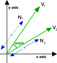
For 2D Vectors
This is relatively simple because there is only one degree of freedom for 2D rotations. If v1 and v2 are normalised so that |v1|=|v2|=1, then,
angle = acos(v1•v2)
where:
- • = 'dot' product (see box on right of page).
- acos = arc cos = inverse of cosine function see trigonometry page.
- |v1|= magnitude of v1.
The only problem is, this won't give all possible values between 0° and 360°, or -180° and +180°. In other words, it won't tell us if v1 is ahead or behind v2, to go from v1 to v2 is the opposite direction from v2 to v1.
In most math libraries acos will usually return a value between 0 and PI (in radians) which is 0° and 180°.
If we want a + or - value to indicate which vector is ahead, then we probably need to use the atan2 function (as explained on this page). using:
angle of 2 relative to 1= atan2(v2.y,v2.x) - atan2(v1.y,v1.x)
For 3D Vectors
Axis Angle Result
This is easiest to calculate using axis-angle representation because:
- the angle is given by acos of the dot product of the two (normalised) vectors: v1•v2 = |v1||v2| cos(angle)
- the axis is given by the cross product of the two vectors, the length of this axis is given by |v1 x v2| = |v1||v2| sin(angle).
this is taken from this discussion.
So, if v1 and v2 are normalised so that |v1|=|v2|=1, then,
angle = acos(v1•v2)
axis = norm(v1 x v2)
If the vectors are parallel (angle = 0 or 180 degrees) then the length of v1 x v2 will be zero because sin(0)=sin(180)=0. In the zero case the axis does not matter and can be anything because there is no rotation round it. In the 180 degree case the axis can be anything at 90 degrees to the vectors so there is a whole range of possible axies.
| angle (degrees) | sin(angle) | cos(angle) | v1•v2 | v1 x v2 |
| 0 | 0 | 1 | 1 | 0,0,0 |
| 90 | 1 | 0 | 0 | unit len |
| 180 | 0 | -1 | -1 | 0,0,0 |
| 270 | -1 | 0 | 0 | unit len |
Quaternion Result
One approach might be to define a quaternion which, when multiplied by a vector, rotates it:
p2=q * p1
This almost works as explained on this page.
However, to rotate a vector, we must use this formula:
p2=q * p1 * conj(q)
where:
- p2 = is a vector representing a point after being rotated
- q = is a quaternion representing a rotation.
- p1= is a vector representing a point before being rotated
This is a bit messy to solve for q, I am therefore grateful to minorlogic for the following approach which converts the axis angle result to a quaternion:
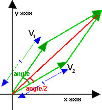
The axis angle can be converted to a quaternion as follows, let x,y,z,w be elements of quaternion, these can be expressed in terms of axis angle as explained here.
angle = arcos(v1•v2/ |v1||v2|)
axis = norm(v1 x v2)
s = sin(angle/2)
x = axis.x *s
y = axis.y *s
z = axis.z *s
w = cos(angle/2)
We can use this half angle trig formula on this page: sin(angle/2) = 0.5 sin(angle) / cos(angle/2)
so substituting in quaternion formula gives:
s = 0.5 sin(angle) / cos(angle/2)
x = norm(v1 x v2).x *s
y = norm(v1 x v2).y *s
z = norm(v1 x v2).z *s
w = cos(angle/2)
multiply x,y,z and w by 2* cos(angle/2) (this will de normalise the quaternion but we can always normalise later)
x = norm(v1 x v2).x * sin(angle)
y = norm(v1 x v2).y * sin(angle)
z = norm(v1 x v2).z * sin(angle)
w = 2 * cos(angle/2) * cos(angle/2)
now substitute half angle trig formula on this page: cos(angle/2) = sqrt(0.5*(1 + cos (angle)))
x = norm(v1 x v2).x * sin(angle)
y = norm(v1 x v2).y * sin(angle)
z = norm(v1 x v2).z * sin(angle)
w = 1 + cos (angle)
because |v1 x v2| = |v1||v2| sin(angle) we can normalise (v1 x v2) by dividing it with sin(angle),
also apply v1•v2 = |v1||v2| cos(angle)so,
x = (v1 x v2).x / |v1||v2|
y = (v1 x v2).y/ |v1||v2|
z = (v1 x v2).z/ |v1||v2|
w = 1 + v1•v2 / |v1||v2|
If v1 and v2 are already normalised then |v1||v2|=1 so,
x = (v1 x v2).x
y = (v1 x v2).y
z = (v1 x v2).z
w = 1 + v1•v2
If v1 and v2 are not already normalised then multiply by |v1||v2| gives:
x = (v1 x v2).x
y = (v1 x v2).y
z = (v1 x v2).z
w = |v1||v2| + v1•v2
Matrix Result
Using the quaternion to matrix conversion here we get:
| 1 - 2*qy2 - 2*qz2 | 2*qx*qy - 2*qz*qw | 2*qx*qz + 2*qy*qw |
| 2*qx*qy + 2*qz*qw | 1 - 2*qx2 - 2*qz2 | 2*qy*qz - 2*qx*qw |
| 2*qx*qz - 2*qy*qw | 2*qy*qz + 2*qx*qw | 1 - 2*qx2 - 2*qy2 |
so substituting the quaternion results above into the matrix we get:
| 1 - 2*(v1 x v2).y2 - 2*(v1 x v2).z2 | 2*(v1 x v2).x*(v1 x v2).y - 2*(v1 x v2).z*(1 + v1•v2) | 2*(v1 x v2).x*(v1 x v2).z + 2*(v1 x v2).y*(1 + v1•v2) |
| 2*(v1 x v2).x*(v1 x v2).y + 2*(v1 x v2).z*(1 + v1•v2) | 1 - 2*(v1 x v2).x2 - 2*(v1 x v2).z2 | 2*(v1 x v2).y*(v1 x v2).z - 2*(v1 x v2).x*(1 + v1•v2) |
| 2*(v1 x v2).x*(v1 x v2).z - 2*(v1 x v2).y*(1 + v1•v2) | 2*(v1 x v2).y*(v1 x v2).z + 2*(v1 x v2).x*(1 + v1•v2) | 1 - 2*(v1 x v2).x2 - 2*(v1 x v2).y2 |
Substituting the following expansions:
(v1 x v2).x = v1.y * v2.z - v2.y * v1.z
(v1 x v2).y = v1.z * v2.x - v2.z * v1.x
(v1 x v2).z = v1.x * v2.y - v2.x * v1.y
(v1 x v2).x2 = v1.y * v2.z * v1.y * v2.z + v2.y * v1.z * v2.y * v1.z - 2 * v2.y * v1.z * v1.y * v2.z
(v1 x v2).y2 = v1.z * v2.x * v1.z * v2.x + v2.z * v1.x * v2.z * v1.x - 2* v2.z * v1.x * v1.z * v2.x
(v1 x v2).z2 = v1.x * v2.y * v1.x * v2.y +v2.x * v1.y * v2.x * v1.y - 2 * v2.x * v1.y * v1.x * v2.y
v1•v2 = v1.x * v2.x + v1.y * v2.y + v1.z * v2.z
This is getting far too complicated ! can anyone help me simplify this?
| Thank you again to minorlogic who gave me the following solution:
Hi ! you can use : And will get some thing : matrix33 RotAngonst vector3& from, const vector3& to ) vector3 v(vs); vector3 vt(v*(1.0f - ca)); matrix33 rotM; vt.x *= v.y; rotM.M12 = vt.x - vs.z; |
Code
axis-angle versionsfrotation angleBetween(sfvec3f v1,sfvec3f v2) {
float angle;
// turn vectors into unit vectors
n1 = v1.norm();
n2 = v2.norm();
angle = Math.acos( sfvec3f.dot(n1,n2) );
// if no noticable rotation is available return zero rotation
// this way we avoid Cross product artifacts
if( Math.abs(angle) < 0.0001 ) return new sfrotation( 0, 0, 1, 0 );
// in this case there are 2 lines on the same axis
if(Math.abs(angle)-Math.pi) < 0.001){
n1 = n1.Rotx( 0.5f );
// there are an infinite number of normals
// in this case. Anyone of these normals will be
// a valid rotation (180 degrees). so I rotate the curr axis by 0.5 radians this way we get one of these normals
}
sfvec3f axis = n1;
axis.cross(n2);
return new sfrotation(axis.x,axis.y,axis.z,angle);
}
quaternion version
/** note v1 and v2 dont have to be nomalised, thanks to minorlogic for telling me about this:
* http://www.euclideanspace.com/maths/algebra/vectors/angleBetween/minorlogic.htm
*/
sfquat angleBetween(sfvec3f v1,sfvec3f v2) {
float d = sfvec3f.dot(v1,v2);
sfvec3f axis = v1;
axis.cross(v2);
float qw = (float)Math.sqrt(v1.len_squared()*v2.len_squared()) + d;
if (qw < 0.0001) { // vectors are 180 degrees apart
return (new sfquat(0,-v1.z,v1.y,v1.x)).norm;
}
sfquat q= new sfquat(qw,axis.x,axis.y,axis.z);
return q.norm();
}
matrix version
sfmatrix angleBetween(sfvec3f v1,sfvec3f v2) {
// turn vectors into unit vectors
n1 = v1.norm();
n2 = v2.norm(); 	sfvec3f vs = new sfvec3f(n1);
vs.cross(n2); // axis multiplied by sin	sfvec3f v = new sfvec3f(vs);
v = v.norm(); // axis of rotation
float ca = dot(n1, n2) ; // cos angle	sfvec3f vt = new sfvec3f(v);	vt.scale((1.0f - ca);	sfmatrix rotM = new sfmatrix();
rotM.m11 = vt.x * v.x + ca;
rotM.m22 = vt.y * v.y + ca;
rotM.m33 = vt.z * v.z + ca;	vt.x *= v.y;
vt.z *= v.x;
vt.y *= v.z;	rotM.m12 = vt.x - vs.z;
rotM.m13 = vt.z + vs.y;
rotM.m21 = vt.x + vs.z;
rotM.m23 = vt.y - vs.x;
rotM.m31 = vt.z - vs.y;
rotM.m32 = vt.y + vs.x;
return rotM;
}
see also code from minorlogic
Project: Polygon Triangulation
LINK:http://www.mpi-inf.mpg.de/~kettner/courses/lib_design_03/proj/polygon_triang.html
Design the interface between data structures that represent simple polygons and generic algorithms that triangulate simple polygons.
The Standard Template Library (STL) [Austern98, SGI-STL] contains several examples of a similar interface design: Iterators are the interface between sequences of items in container classes and generic algorithms on sequences. However, they (usually) do not modify the container. Among the container classes some modifying functions, e.g., insert or remove, describe a standardized interface for modifying the container classes and can be used for generic algorithms on container classes. This project is expected to design a generic interface in the same spirit for triangulating polygons.
We start with a set of data structures that can represent a simple polygon, and with a set of algorithms that can triangulate it. We suggest to use the Computational Geometry Algorithms Library (CGAL) <www.cgal.org> [Fabri99] as a source of data structures and algorithms in geometry and also as a platform for realizing this project. Possible data structures could be:
- A
std::listof 2D points. - The class
CGAL::Polygon_2. - An individual facet of a 3D polyhedral surface, e.g., the class
CGAL::Polyhedron_3. - While working with the triangulation data structure underlying the class
CGAL::Triangulation_2one can end up in the situation to triangulate a polygonal hole in the triangulation structure.
All these representations would be for simple polygons without holes. An optional extension would be to extend this project to polygons with holes as they can be represented with:
- A
std::listofstd::list's of 2D points, where the first list is the outer boundary of the polygon and all succeeding lists are the inner boundaries of holes in the polygon, one list per hole. - The class
CGAL::Planar_map_2can contain faces with holes. - The class
CGAL::Nef_polyhedron_2can contain faces with holes.
Examples of algorithms that triangulate polygons are:
- Ear-cutting algorithm: An ear is a triangle formed by two consecutive edges of the polygon with a convex angle that contains no other point of a polygon. There exist always at least two ears in a polygon. An ear can be cut from the polygon, reducing its size and thus triangulating it.
- A sweep-line algorithm, see [Chapter 3, deBerg00].
- The constrained triangulation in CGAL. It creates a triangulation of the convex hull of a set of points respecting a set of constrained edges that have to be present in the triangulation, which would be the polygon boundary edges here. Afterwards the triangles in the polygon interior have to be selected, i.e., distinguished from those outside of the polygon.
Clearly iterators can be used in examining the input polygon. The new part will be the modifying part of the algorithms; where do we create and store the result triangles:
- For a single polygon we might just write triangles to an output iterator, for example, for storage in a container or for rendering.
- For polygons embedded in a data structure, such as a triangulation or a polyhedral surface, one wants the result triangles to replace the original polygon and to have the proper neighborhood pointers.
The goal of the project is to design the interface and to realize some of the data structures and algorithms, possibly based on the already existing CGAL implementations. The task includes:
- Analyse the set of operations of each agorithm and how it could be implemented for each data structure considered.
- Find a common set (or several sets) of operations that support the different combinations.
- Implement the interface for the data structures, possibly with adaptors for the existing data structures in CGAL.
- Implement the algorithm based on this interface, maybe also with adaptors to the already existing algorithms in CGAL.
- Test your generic algorithms on the different representations.
- Document the design, for example, in the style of CGAL or using Doxygen.
Prerequisites
This project requires interest in geometry or graphics and some knowledge of geometric algorithms. Since CGAL will be covered later in the course, it might be necessary to learn about CGAL prior to that.
References
- [Austern98]
- Mathew H. Austern. Generic Programming and the STL: Using and Extending the C++ Standard Template Library. Addison-Wesley, 1998.
- [SGI-STL]
- Silicon Graphics Computer Systems, Inc. Standard Template Library Programmer's Guide. http://www.sgi.com/tech/stl/.
- [Fabri99]
- Andreas Fabri, Geert-Jan Giezeman, Lutz Kettner, Stefan Schirra, and Sven Schönherr. On the Design of CGAL, the Computational Geometry Algorithms Library. Software -- Practice and Experience, submitted 1999, to appear. (also available as technical report)
- [deBerg00]
- Mark de Berg, Marc van Kreveld, Mark Overmars, and Otfried Schwarzkopf. Computational Geometry: Algorithms and Applications. Springer, 2nd edition, 2000.
- Mathew H. Austern. Generic Programming and the STL: Using and Extending the C++ Standard Template Library. Addison-Wesley, 1998.
K-3D
|
About K-3D
|
Using K-3D
|
Contributing to K-3D
|
|
K-3D News
K-3D Joins Software Freedom Conservancy Google Summer of Code 2008 Report Mac OSX Installer Released! K-3D 0.7 Released! Keep in Touch |
贝塞尔曲线
在數學的數值分析領域中,貝茲曲線(Bézier curve)是電腦圖形學中相當重要的參數曲線。更高維度的廣泛化貝茲曲線就稱作貝茲曲面,其中貝茲三角是一種特殊的實例。
貝茲曲線於1962年,由法國工程師皮埃爾·貝茲(Pierre Bézier)所廣泛發表,他運用貝茲曲線來為汽車的主體進行設計。貝茲曲線最初由 Paul de Casteljau 於1959年運用 de Casteljau 演算法開發,以穩定數值的方法求出貝茲曲線。
目录[隐藏] |
[编辑] 實例說明
[编辑] 線性貝茲曲線
給定點 P0、P1,線性貝茲曲線只是一條兩點之間的直線。這條線由下式給出:
且其等同於線性插值。
[编辑] 二次方貝茲曲線
二次方貝茲曲線的路徑由給定點 P0、P1、P2 的函數 B(t) 追蹤:
![\mathbf{B}(t) = (1 - t)^{2}\mathbf{P}_0 + 2t(1 - t)\mathbf{P}_1 + t^{2}\mathbf{P}_2 \mbox{ , } t \in [0,1]]() 。
。
TrueType 字型就運用了以貝茲樣條組成的二次貝茲曲線。
[编辑] 三次方貝茲曲線
P0、P1、P2、P3 四個點在平面或在三維空間中定義了三次方貝茲曲線。曲線起始於 P0 走向 P1,並從 P2 的方向來到 P3。一般不會經過 P1 或 P2;這兩個點只是在那裡提供方向資訊。 P0 和 P1 之間的間距,決定了曲線在轉而趨進 P3 之前,走向 P2 方向的「長度有多長」。
曲線的參數形式為:
![\mathbf{B}(t)=\mathbf{P}_0(1-t)^3+3\mathbf{P}_1t(1-t)^2+3\mathbf{P}_2t^2(1-t)+\mathbf{P}_3t^3 \mbox{ , } t \in [0,1]]() 。
。
現代的成象系統,如 PostScript、Asymptote 和 Metafont,運用了以貝茲樣條組成的三次貝茲曲線,用來描繪曲線輪廓。
[编辑] 一般化
n 階貝茲曲線可如下推斷。給定點 P0、P1、…、Pn,其貝茲曲線即
![\mathbf{B}(t)=\sum_{i=0}^n {n\choose i}\mathbf{P}_i(1-t)^{n-i}t^i =\mathbf{P}_0(1-t)^n+{n\choose 1}\mathbf{P}_1(1-t)^{n-1}t+\cdots+\mathbf{P}_nt^n \mbox{ , } t \in [0,1]]() 。
。
例如 n = 5:
![\mathbf{B}(t)=\mathbf{P}_0(1-t)^5+5\mathbf{P}_1t(1-t)^4+10\mathbf{P}_2t^2(1-t)^3+10\mathbf{P}_3t^3(1-t)^2+5\mathbf{P}_4t^4(1-t)+\mathbf{P}_5t^5 \mbox{ , } t \in [0,1]]() 。
。
如上公式可如下遞歸表達: 用  表示由點 P0、P1、…、Pn 所決定的貝茲曲線。則
用平常話來說,n 階的貝茲曲線,即雙 n - 1 階貝茲曲線之間的插值。
[编辑] 術語
一些關於參數曲線的術語,有
即多項式
又稱作 n 階的伯恩斯坦基底多項式,定義 00 = 1。
點 Pi 稱作貝茲曲線的控制點。多邊形以帶有線的貝茲點連接而成,起始於 P0 並以 Pn 終止,稱作貝茲多邊形(或控制多邊形)。貝茲多邊形的凸包(convex hull)包含有貝茲曲線。
[编辑] 註解
- 開始於 P0 並結束於 Pn 的曲線,即所謂的端點插值法屬性。
- 曲線是直線的充分必要條件是所有的控制點都位在曲線上。同樣的,貝茲曲線是直線的充分必要條件是控制點共線。
- 曲線的起始點(結束點)相切於貝茲多邊形的第一節(最後一節)。
- 一條曲線可在任意點切割成兩條或任意多條子曲線,每一條子曲線仍是貝茲曲線。
- 一些看似簡單的曲線(如圓)無法以貝茲曲線精確的描述,或分段成貝茲曲線(雖然當每個內部控制點對單位圓上的外部控制點水平或垂直的的距離為
![4\left(\sqrt{2} -1\right)/3]() 時,分成四段的貝茲曲線,可以小於千分之一的最大半徑誤差近似於圓)。
時,分成四段的貝茲曲線,可以小於千分之一的最大半徑誤差近似於圓)。
- 位於固定偏移量的曲線(來自給定的貝茲曲線),又稱作偏移曲線(假平行於原來的曲線,如兩條鐵軌之間的偏移)無法以貝茲曲線精確的形成(某些瑣屑實例除外)。無論如何,現存的啟發法通常可為實際用途中給出近似值。
[编辑] 建構貝茲曲線
[编辑] 線性曲線
![線性貝茲曲線演示動畫,t in [0,1]](http://upload.wikimedia.org/wikipedia/commons/8/89/Bezier_1_big.gif) |
| 線性貝茲曲線演示動畫,t in [0,1] |
線性貝茲曲線函數中的 t 會經過由 P0 至 P1 的 B(t) 所描述的曲線。例如當 t=0.25 時,B(t) 即一條由點 P0 至 P1 路徑的四分之一處。就像由 0 至 1 的連續 t,B(t) 描述一條由 P0 至 P1 的直線。
[编辑] 二次曲線
為建構二次貝茲曲線,可以中介點 Q0 和 Q1 作為由 0 至 1 的 t:
- 由 P0 至 P1 的連續點 Q0,描述一條線性貝茲曲線。
- 由 P1 至 P2 的連續點 Q1,描述一條線性貝茲曲線。
- 由 Q0 至 Q1 的連續點 B(t),描述一條二次貝茲曲線。
 |
![二次貝茲曲線演示動畫,t in [0,1]](http://upload.wikimedia.org/wikipedia/commons/2/2d/Bezier_2_big.gif) |
|
| 二次貝茲曲線的結構 | 二次貝茲曲線演示動畫,t in [0,1] |
[编辑] 高階曲線
為建構高階曲線,便需要相應更多的中介點。對於三次曲线,可由線性貝茲曲線描述的中介點 Q0、Q1、Q2,和由二次曲線描述的點 R0、R1 所建構:
 |
![三次貝茲曲線演示動畫,t in [0,1]](http://upload.wikimedia.org/wikipedia/commons/f/ff/Bezier_3_big.gif) |
|
| 三次貝茲曲線的結構 | 三次貝茲曲線演示動畫,t in [0,1] |
對於四次曲線,可由線性貝茲曲線描述的中介點 Q0、Q1、Q2、Q3,由二次貝茲曲線描述的點 R0、R1、R2,和由三次貝茲曲線描述的點 S0、S1 所建構:
 |
![四次貝茲曲線演示動畫,t in [0,1]](http://upload.wikimedia.org/wikipedia/commons/7/7d/Bezier_4_big.gif) |
|
| 四次貝茲曲線的結構 | 四次貝茲曲線演示動畫,t in [0,1] |
(還可參閱五階貝茲曲線的構成。)
[编辑] 應用
[编辑] 電腦繪圖
贝塞尔曲线被广泛地在计算机图形中用来为平滑曲线建立模型。
二次和三次贝塞尔曲线最为常见
[编辑] 程式範例
下列程式碼為一簡單的實際運用範例,展示如何使用 C 標出三次方貝茲曲線。注意,此處僅簡單的計算多項式係數,並讀盡一系列由 0 至 1 的 t 值;實踐中一般不會這麼做,遞歸求解通常會更快速——以更多的記憶體為代價,花費較少的處理器時間。不過直接的方法較易於理解並產生相同結果。以下程式碼已使運算更為清晰。實踐中的最佳化會先計算係數一次,並在實際計算曲線點的迴圈中反複使用。此處每次都會重新計算,損失了效率,但程式碼更清楚易讀。
曲線的計算可在曲線陣列上將相連點畫上直線——點越多,曲線越平滑。
在部分架構中,下以程式碼也可由動態程式設計進行最佳化。舉例來說,dt 是一個常數,cx * t 則等同於每次反覆就修改一次常數。經反覆應用這種最佳化後,迴圈可被重寫為沒有任何乘法(雖然這個過程不是穩定數值的)。
/*
產生三次方貝茲曲線的程式碼
*/
typedef struct
{
float x;
float y;
}
Point2D;
/*
cp 在此是四個元素的陣列:
cp[0] 為起始點,或上圖中的 P0
cp[1] 為第一個控制點,或上圖中的 P1
cp[2] 為第二個控制點,或上圖中的 P2
cp[3] 為結束點,或上圖中的 P3
t 為參數值,0 <= t <= 1
*/
Point2D PointOnCubicBezier( Point2D* cp, float t )
{
float   ax, bx, cx;
float   ay, by, cy;
float   tSquared, tCubed;
Point2D result;
/* 計算多項式係數 */
cx = 3.0 * (cp[1].x - cp[0].x);
bx = 3.0 * (cp[2].x - cp[1].x) - cx;
ax = cp[3].x - cp[0].x - cx - bx;
cy = 3.0 * (cp[1].y - cp[0].y);
by = 3.0 * (cp[2].y - cp[1].y) - cy;
ay = cp[3].y - cp[0].y - cy - by;
/* 計算位於參數值 t 的曲線點 */
tSquared = t * t;
tCubed = tSquared * t;
result.x = (ax * tCubed) + (bx * tSquared) + (cx * t) + cp[0].x;
result.y = (ay * tCubed) + (by * tSquared) + (cy * t) + cp[0].y;
return result;
}
/*
ComputeBezier 以控制點 cp 所產生的曲線點,填入 Point2D 結構的陣列。
呼叫者必須分配足夠的記憶體以供輸出結果,其為 <sizeof(Point2D) numberOfPoints>
*/
void ComputeBezier( Point2D* cp, int numberOfPoints, Point2D* curve )
{
float   dt;
int	    i;
dt = 1.0 / ( numberOfPoints - 1 );
for( i = 0; i < numberOfPoints; i++)
curve[i] = PointOnCubicBezier( cp, i*dt );
}
另一種貝茲曲線的應用是在動畫中,描述物件的運動路徑等等。此處,曲線的 x、y 位置不用來標示曲線,但用來表示圖形位置。當用在這種形式時,連續點之間的距離會變的更為重要,且大多不是平均比例。點將會串的更緊密,控制點更接近每一個點,而更為稀疏的控制點會散的更開。如果需要線性運動速度,進一步處理時就需要循所需路徑將點平均分散。
[编辑] 有理貝茲曲線
有理貝茲增加可調節的權重,以提供更近似於隨意的形狀。分子是加權的伯恩斯坦形式貝茲曲線,而分母是加權的伯恩斯坦多項式的總和。
給定 n + 1 控制點 Pi,有理貝茲曲線可如下描述:
或簡單的
[编辑] 參閱
- de Casteljau算法
- 樣條
- 貝茲樣條
- 貝茲曲面
- 貝茲三角
- NURBS
- string art,Bézier curves are also formed by many common forms of string art, where strings are looped across a frame of nails.
- 埃爾米特曲線
[编辑] 參考文獻
- Paul Bourke: Bézier curves, http://astronomy.swin.edu.au/~pbourke/curves/bezier/
- Donald Knuth: Metafont: the Program, Addison-Wesley 1986, pp. 123-131. Excellent discussion of implementation details; available for free as part of the TeX distribution.
- Dr Thomas Sederberg, BYU Bézier curves, http://www.tsplines.com/resources/class_notes/Bezier_curves.pdf
- J.D. Foley et al.: Computer Graphics: Principles and Practice in C (2nd ed., Addison Wesley, 1992)
【数学中国推荐】几何学-微分几何
Point in triangle test
Same Side Technique
A common way to check if a point is in a triangle is to find the vectors connecting the point to each of the triangle's three vertices and sum the angles between those vectors. If the sum of the angles is 2*pi then the point is inside the triangle, otherwise it is not. It works, but it is very slow. This text explains a faster and much easier method.
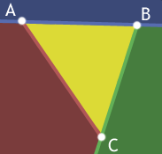 |
First off, forgive the nasty coloring. I'm really sorry about it. Honest.
Okay, A B C forms a triangle and all the points inside it are yellow. Lines AB, BC, and CA each split space in half and one of those halves is entirely outside the triangle. This is what we'll take advantage of. For a point to be inside the traingle A B C it must be below AB and left of BC and right of AC. If any one of these tests fails we can return early. |
But, how do we tell if a point is on the correct side of a line? I'm glad you asked.

If you take the cross product of [B-A] and [p-A], you'll get a vector pointing out of the screen. On the other hand, if you take the cross product of [B-A] and [p'-A] you'll get a vector pointing into the screen. Ah ha! In fact if you cross [B-A] with the vector from A to any point above the line AB, the resulting vector points out of the screen while using any point below AB yields a vector pointing into the screen. So all we need to do to distinguish which side of a line a point lies on is take a cross product.
The only question remaining is: how do we know what direction the cross product should point in? Because the triangle can be oriented in any way in 3d-space, there isn't some set value we can compare with. Instead what we need is a reference point - a point that we know is on a certain side of the line. For our triangle, this is just the third point C.
So, any point p where [B-A] cross [p-A] does not point in the same direction as [B-A] cross [C-A] isn't inside the triangle. If the cross products do point in the same direction, then we need to test p with the other lines as well. If the point was on the same side of AB as C and is also on the same side of BC as A and on the same side of CA as B, then it is in the triangle.
Implementing this is a breeze. We'll make a function that tells us if two points are on the same side of a line and have the actual point-in-triangle function call this for each edge.
function SameSide(p1,p2, a,b)
            cp1 = CrossProduct(b-a, p1-a)
            cp2 = CrossProduct(b-a, p2-a)
            if DotProduct(cp1, cp2) >= 0 then return true
            else return false
            function PointInTriangle(p, a,b,c)
            if SameSide(p,a, b,c) and SameSide(p,b, a,c)
            and SameSide(p,c, a,b) then return true
            else return false
|
It's simple, effective and has no square roots, arc cosines, or strange projection axis determination nastiness.
Barycentric Technique
The advantage of the method above is that it's very simple to understand so that once you read it you should be able to remember it forever and code it up at any time without having to refer back to anything. It's just - hey the point has to be on the same side of each line as the triangle point that's not in the line. Cake.
Well, there's another method that is also as easy conceptually but executes faster. The downside is there's a little more math involved, but once you see it worked out it should be no problem.
So remember that the three points of the triangle define a plane in space. Pick one of the points and we can consider all other locations on the plane as relative to that point. Let's go with A -- it'll be our origin on the plane. Now what we need are basis vectors so we can give coordinate values to all the locations on the plane. We'll pick the two edges of the triangle that touch A, (C - A) and (B - A). Now we can get to any point on the plane just by starting at A and walking some distance along (C - A) and then from there walking some more in the direction (B - A).
With that in mind we can now describe any point on the plane as
P = A + u * (C - A) + v * (B - A)
Notice now that if u or v < 0 then we've walked in the wrong direction and must be outside the triangle. Also if u or v > 1 then we've walked too far in a direction and are outside the triangle. Finally if u + v > 1 then we've crossed the edge BC again leaving the triangle.
Given u and v we can easily calculate the point P with the above equation, but how can we go in the reverse direction and calculate u and v from a given point P? Time for some math!
    P = A + u * (C - A) + v * (B - A)       // Original equation
(P - A) = u * (C - A) + v * (B - A)     // Subtract A from both sides
v2 = u * v0 + v * v1                    // Substitute v0, v1, v2 for less writing
// We have two unknowns (u and v) so we need two equations to solve
// for them.  Dot both sides by v0 to get one and dot both sides by
// v1 to get a second.
(v2) . v0 = (u * v0 + v * v1) . v0
(v2) . v1 = (u * v0 + v * v1) . v1
// Distribute v0 and v1
v2 . v0 = u * (v0 . v0) + v * (v1 . v0)
v2 . v1 = u * (v0 . v1) + v * (v1 . v1)
// Now we have two equations and two unknowns and can solve one
// equation for one variable and substitute into the other.  Or
// if you're lazy like me, fire up Mathematica and save yourself
// some handwriting.
Solve[v2.v0 == {u(v0.v0) + v(v1.v0), v2.v1 == u(v0.v1) + v(v1.v1)}, {u, v}]
u = ((v1.v1)(v2.v0)-(v1.v0)(v2.v1)) / ((v0.v0)(v1.v1) - (v0.v1)(v1.v0))
v = ((v0.v0)(v2.v1)-(v0.v1)(v2.v0)) / ((v0.v0)(v1.v1) - (v0.v1)(v1.v0))
Here's an implementation in Flash that you can play with. :)
|
|
// Compute vectors
                v0 = C - A
                v1 = B - A
                v2 = P - A
                // Compute dot products
                dot00 = dot(v0, v0)
                dot01 = dot(v0, v1)
                dot02 = dot(v0, v2)
                dot11 = dot(v1, v1)
                dot12 = dot(v1, v2)
                // Compute barycentric coordinates
                invDenom = 1 / (dot00 * dot11 - dot01 * dot01)
                u = (dot11 * dot02 - dot01 * dot12) * invDenom
                v = (dot00 * dot12 - dot01 * dot02) * invDenom
                // Check if point is in triangle
                return (u > 0) && (v > 0) && (u + v < 1)
|
The algorithm outlined here follows one of the techniques described in Realtime Collision Detection. You can also find more information about Barycentric Coordinates at Wikipedia and MathWorld.


 , the
, the ![v=[a; b; c],](http://mathworld.wolfram.com/images/equations/Point-PlaneDistance/NumberedEquation2.gif)
![w=-[x-x_0; y-y_0; z-z_0].](http://mathworld.wolfram.com/images/equations/Point-PlaneDistance/NumberedEquation3.gif)
 onto
onto  gives the distance
  from the point to the plane as


 is on the same side of the plane as the normal vector
  and negative if it is on the opposite side.
 is the unit normal vector. Therefore, the distance of the plane from the origin is simply given by
  (Gellert et al. 1989, p. 541).
  for
for  , 2, 3, compute the unit normal
 to the plane containing the three points is given by
 is any of the three points. Expanding out the coordinates shows that


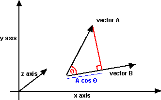
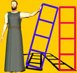
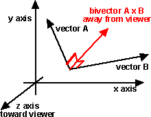
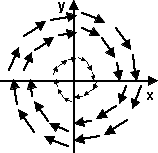


![\mathbf{B}(t)=\mathbf{P}_0 + (\mathbf{P}_1-\mathbf{P}_0)t=(1-t)\mathbf{P}_0 + t\mathbf{P}_1 \mbox{ , } t \in [0,1]](http://upload.wikimedia.org/math/0/5/c/05c4210c69ffb1358ceb8eb83a1a06fe.png)
![\mathbf{B}(t) = (1 - t)^{2}\mathbf{P}_0 + 2t(1 - t)\mathbf{P}_1 + t^{2}\mathbf{P}_2 \mbox{ , } t \in [0,1]](http://upload.wikimedia.org/math/8/a/d/8adc5cc34ea9649d6e546043fce9c407.png) 。
。 ![\mathbf{B}(t)=\mathbf{P}_0(1-t)^3+3\mathbf{P}_1t(1-t)^2+3\mathbf{P}_2t^2(1-t)+\mathbf{P}_3t^3 \mbox{ , } t \in [0,1]](http://upload.wikimedia.org/math/5/9/7/597ecc5022fa7ab65509d5edfa9c148c.png) 。
。 ![\mathbf{B}(t)=\sum_{i=0}^n {n\choose i}\mathbf{P}_i(1-t)^{n-i}t^i =\mathbf{P}_0(1-t)^n+{n\choose 1}\mathbf{P}_1(1-t)^{n-1}t+\cdots+\mathbf{P}_nt^n \mbox{ , } t \in [0,1]](http://upload.wikimedia.org/math/5/c/d/5cdbbad5d4698c786a3f02a1b9fb5f2d.png) 。
。 ![\mathbf{B}(t)=\mathbf{P}_0(1-t)^5+5\mathbf{P}_1t(1-t)^4+10\mathbf{P}_2t^2(1-t)^3+10\mathbf{P}_3t^3(1-t)^2+5\mathbf{P}_4t^4(1-t)+\mathbf{P}_5t^5 \mbox{ , } t \in [0,1]](http://upload.wikimedia.org/math/d/b/4/db41ef611ab1eedb0606d9bce9012c30.png) 。
。 
![\mathbf{B}(t) = \sum_{i=0}^n \mathbf{P}_i\mathbf{b}_{i,n}(t),\quad t\in[0,1]](http://upload.wikimedia.org/math/3/d/8/3d8f42d9608ecbd44e2f57758d159eb2.png)

 時,分成四段的貝茲曲線,可以小於千分之一的最大半徑誤差近似於圓)。


August 31st, 2008 at 3:06 am
Hi,
Thanks for the great instructions on compiling touchlib, but one question-do I need Visual Studio 05, or will Visual C++ Express, Dev C++, or another compiler work as well? Thx,
rbedi100
September 7th, 2008 at 7:22 pm
Also it works with Visual Studio 2008. Thanks.
September 13th, 2008 at 6:10 pm
hi just wandering is the touchlib software free, and does it means you can use a camera too to control it.
September 13th, 2008 at 11:42 pm
@rbedi100:
I’m not sure if it will work on Visual Studio Express or other ‘free’ IDE’s.
@mr b:
The software is free and released under GPL2. You can control the camera parameters if needed.
October 25th, 2008 at 11:07 am
Hi, i have done as this tutorial, but when i compile the touchlib ,there are lots of errors in “C:\Program Files\Microsoft SDKs\Windows\v6.1\Include\intsafe.h(1278) : error C2061 ..” .
and when i compile “configapp”,it’s succes!
is my intsafe.h file have sth wrong?
thank you!
October 31st, 2008 at 11:42 am
@Richard Z:
Strange error, are you using visual studio 2005 (or express?)?
I guess you’ve set the include directories properly?
C:\Program Files\Microsoft SDKs\Windows\v6.1\Samples\Multimedia\DirectShow\BaseClasses
and
C:\Program Files\Microsoft SDKs\Windows\v6.1\Include
with this library directory:
C:\Program Files\Microsoft SDKs\Windows\v6.1\Lib
December 30th, 2008 at 11:59 am
Hi, i have done as this tutorial, but when i compile the touchlib .compling can pass but i have a link problem:
and i use visual studio 2005 express
1>DSVLCaptureFilter.obj : error LNK2019: unresolved external symbol __imp__CoInitialize@4 referenced in function “public: __thiscall DSVLCaptureFilter::DSVLCaptureFilter(char *)” (??0DSVLCaptureFilter@@QAE@PAD@Z)
January 12th, 2009 at 4:27 pm
@zousong:
It seems like it can not find the DSVL.lib file, check your path settings in the environmental variables:
It should be this:
name: “DSVL_HOME”
value: “C:\_libraries\dsvl-0.0.8c”
March 14th, 2009 at 8:57 am
I m not getting the directry as
1.C:\Program Files\Microsoft Platform SDK for Windows Server 2003 R2\Include
2.C:\Program Files\Microsoft Platform SDK for Windows Server 2003 R2\Samples\Multimedia\DirectShow\BaseClasses
HOw to add these directries…plz suggest me.thanks
March 14th, 2009 at 4:31 pm
dear Harry van der Veen
i want to install touch lib on window xp.
i used the Touchlib compiling instructions Multigesture_net.htm.
but afterall we r getting the same error as
Error 23 error C2065: ‘m_pSchedule’ : undeclared identifier c:\program files\microsoft sdks\windows\v6.1\samples\multimedia\directshow\baseclasses\refclock.h 139
Error 79 error C2327: ‘CBaseReferenceClock::LPCTSTR’ : is not a type name, static, or enumerator c:\program files\microsoft sdks\windows\v6.1\samples\multimedia\directshow\baseclasses\sysclock.h 25
plz suggest me as poss as.
thanking u
March 26th, 2009 at 5:11 am
@ghanshyam
You need to have the baseclasses directory (samples/multimedia/directshow) before the sdk include directory.
March 26th, 2009 at 5:18 am
Ghanshyam Says:
March 14th, 2009 at 8:57 am
I m not getting the directry as
1.C:\Program Files\Microsoft Platform SDK for Windows Server 2003 R2\Include
2.C:\Program Files\Microsoft Platform SDK for Windows Server 2003 R2\Samples\Multimedia\DirectShow\BaseClasses
Mine look like this:
C:\Program Files\Microsoft SDKs\Windows\v6.0\Samples\Multimedia\DirectShow\BaseClasses
and
C:\Program Files\Microsoft SDKs\Windows\v6.0\Include
April 10th, 2009 at 8:17 am
Thanx for the great instruction…
I followed your steps but am getting the errors below. Please advice.
Compiling…
cl : Command line warning D9035 : option ‘Wp64′ has been deprecated and will be removed in a future release
DSVLCaptureFilter.cpp
c:\documents and settings\g\desktop\new folder\multitouch\google\touchlib-src-win32-20071106\touchlib\include\dsvlcapturefilter.h(9) : fatal error C1083: Cannot open include file: ’streams.h’: No such file or directory
FilterFactory.cpp
c:\documents and settings\g\desktop\new folder\multitouch\google\touchlib-src-win32-20071106\touchlib\include\videowrapperfilter.h(8) : fatal error C1083: Cannot open include file: ’streams.h’: No such file or directory
VideoWrapperFilter.cpp
c:\documents and settings\g\desktop\new folder\multitouch\google\touchlib-src-win32-20071106\touchlib\include\videowrapperfilter.h(8) : fatal error C1083: Cannot open include file: ’streams.h’: No such file or directory
Generating Code…
April 13th, 2009 at 5:41 am
To Tan :
Just include iostream instead
To Laurence Muller :
Thank you for the instructions
To Anyone please :
Does anyone see an error in the code below? i keep getting an error at ‘_AUX_RGBImageRec *Image;’ . The code below is from textures.h. And the error am getting is : error C2143: syntax error : missing ‘;’ before ‘*’. Am sure its sumtin stupid, i just dont see it tho.
#include
class COGLTexture
{
public:
COGLTexture();
~COGLTexture();
#ifdef WIN32
_AUX_RGBImageRec *Image;
#endif
unsigned int GetID();
void LoadFromFile(char *filename);
void SetActive();
int GetWidth();
int GetHeight();
private:
int Width, Height;
unsigned int ID;
bool bInitialized;
};
April 13th, 2009 at 11:53 am
It seems that the most recent windows SDK (v6.1) no longer supports glaux.h which is required by the demo projects in touchlib. Looking a bit around on internet it seems that it should no longer be used. To solve the problem I copied glaux.h and glaux.lib from the previous SDK (for Windows Server 2003 R2).
April 13th, 2009 at 6:08 pm
correction , the first line is: #include
April 13th, 2009 at 6:09 pm
GL/gl.h
April 17th, 2009 at 8:02 pm
Hi I am getting a lot of compile errors with refclock.h
I am using VS2008 btw but that should make no odds…
any clues
Error 44 error C2061: syntax error : identifier ‘CAMSchedule’ c:\program files\microsoft sdks\windows\v6.1\samples\multimedia\directshow\baseclasses\refclock.h 80 touchlib
for example
I am trying to build touchlib
April 21st, 2009 at 5:22 am
I had the same problem as LBDL’s. Found the solution here:
http://social.msdn.microsoft.com/forums/en-US/windowsdirectshowdevelopment/thread/5da8f0b8-d2a9-4caf-81e1-7f5788fa1c00/
The solution work for xp and vista